资料下载

使用步进电机拉下无花果树枝以吓跑鸟类和松鼠
描述
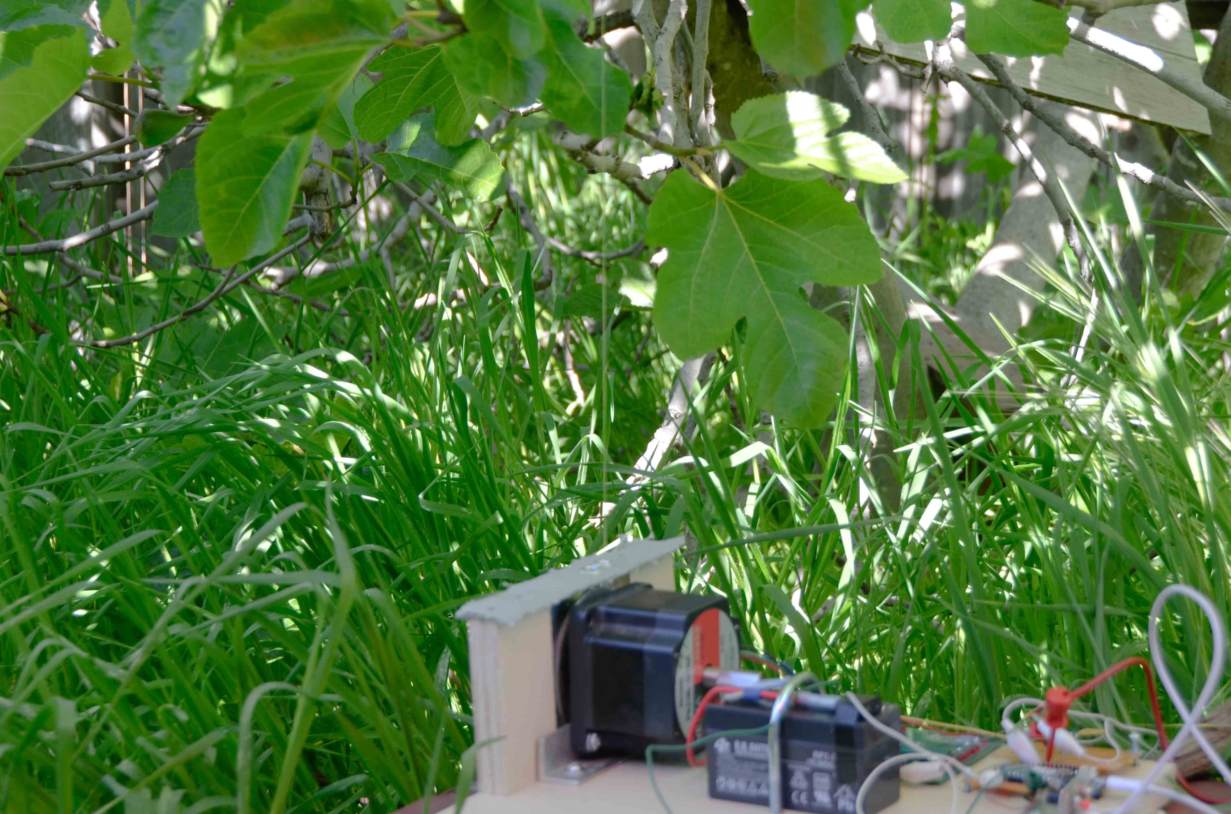
该项目使用步进电机拉下无花果树枝,以吓跑鸟类和松鼠。即摇肢。
我知道摇动肢体会很好地吓唬鸟类和松鼠,因为我已经使用附在肢体上的手动钓鱼线这样做了。
我对 MKR1000 进行了编程,使其以简单的模式摇动肢体。
一个周期定义为步进电机在线路上下拉一次或向上释放一次,即电机沿一个方向移动为下拉,另一个方向为向上释放。
一对循环是肢体的一次下拉和一次向上释放。
由于不同的挫折,我最初的计划比我有时间进行的更广泛。内容如下。
循环将成组进行,例如每组 5 对,暂停,然后是另一组 5 对。
这将被称为序列。我从经验中知道这种顺序。
½ 小时后,另一个序列发生。
将描述报告中提交的周期。
报告中提交的步进电机序列由八个方向变化和每个方向变化内的四个步骤组成。
此序列构成一次执行。
每次执行都是通过手动设置微控制器复位来开始的。
最初的计划是由 MKR1000 控制的一系列执行

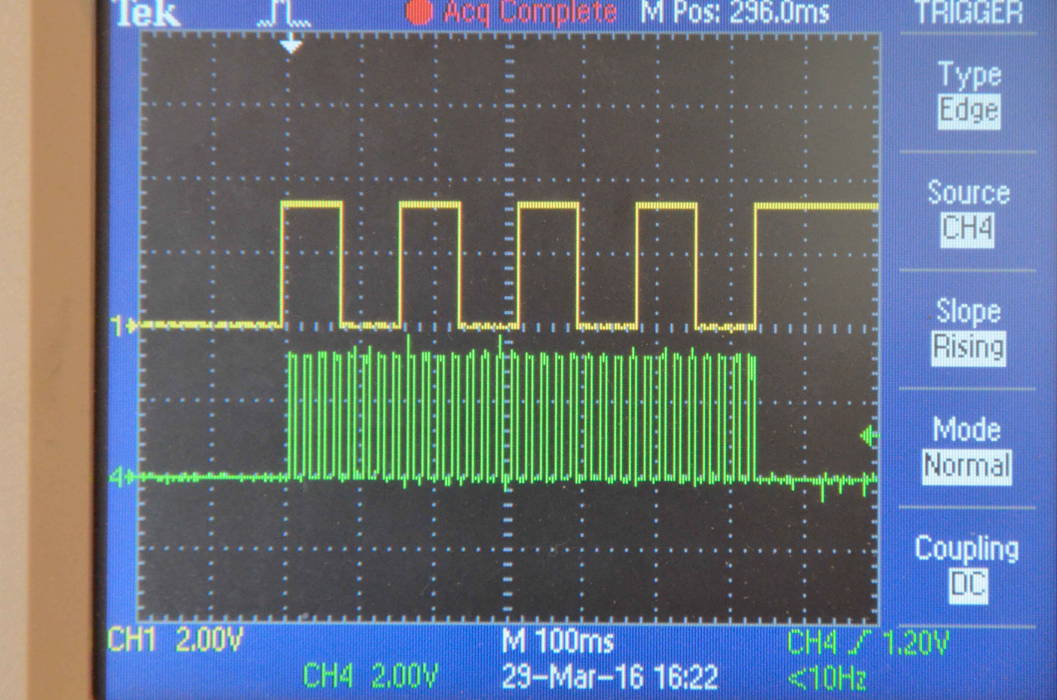
方向和步进波形
上面的波形显示方向。当电压为 3.3 V 时电机逆时针旋转,当电压为 0.0 V 时电机逆时针旋转。下面的波形显示了步骤。当电压向正方向变化时,电机步进。我们可以 在每个方向观察四个步骤。这张照片中的步长周期为 20 毫秒。(我最后用了 10 毫秒。)

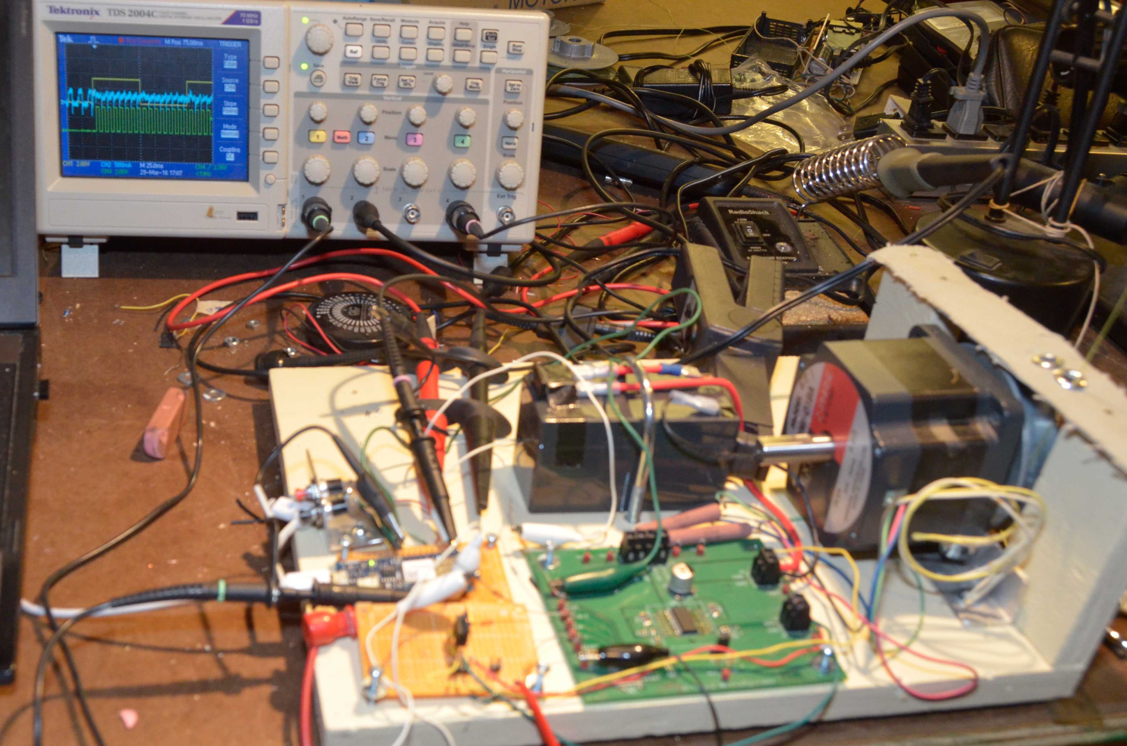
开发设置

阿杜诺 MKR1000
数字输入输出
电机步进引脚 6
电机方向引脚 1
电机驱动器复位引脚 0
中断引脚 A1 和 A2
更改参数以优化惊吓鸟类和松鼠的顺序以及本报告中使用的值
½ 步进时间 T0 = 5 ms
一个方向的时间 T1 = 80 ms
一个周期的时间 T2 = 1280 ms
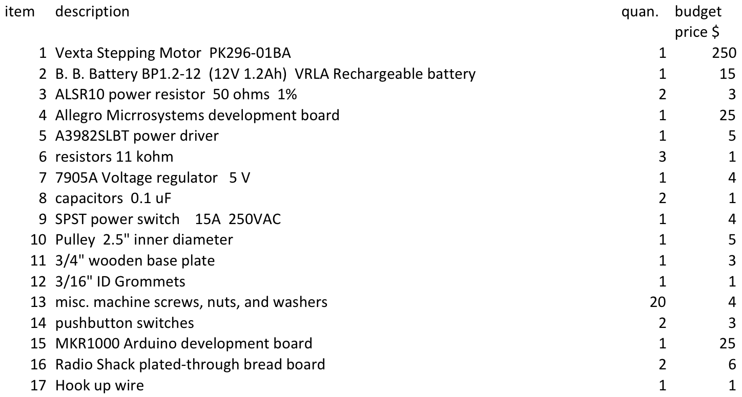
材料清单

我的项目延迟的原因示例:
最初,我烧坏了两个电机驱动芯片。当我订购并安装这两个芯片时,两周已经过去了。
当我尝试安装中断时,我通过william hill官网 发现其中一个附加函数存在错误。那花了 1.5 天。
我花了很多时间来尝试让 Serial.print 工作。我终于放弃了。该william hill官网 表示 serial.print 也没有工作。
在另外两个例子中,我按照所有的编码指南编写了一个程序,但结果是错误的。我有一种感觉,我违反了一些未记录的错误。
过去,我使用 Atmega 16 微控制器的软件编写代码来控制此步进电机。这是一个更通用的开发软件,很好但超出了我们对这个 MKR100 项目的规则,更重要的是为了节省时间,它很稳定。
但是,也许我们应该预料到使用此 Beta 版 MKR1000 会出现错误。
源代码
/* Step and direction
Steps the motor in one direction, then steps it in the other direction.
the purpose of this code is a simple test of the power driver and MKR1000
 The circuit:
STEP is from pin 6 to Allegro step.
DIRECTION is from pin 1.
RESET is from pin 0
 created 3/29/16
 by Art Wagner
 */
// constants won't change. Used here to set a pin number :
const int STEP6 =  6;      // the number of the STEP pin
const int DIR1 =  1;      // the number of the DIRECTION pin
const int RESET0 =  0;      // the number of the RESET pin
// Variables will change : We are assigning initial digital values
int stepState = LOW;
int dirState = HIGH;
int resetState = HIGH;
unsigned long tT0;        //previous time read for the step
unsigned long tT1;        //previous time read for the directi
unsigned long tT2;        //
const long T0 = 5;           //T0 is the time between change in step signal. 10 10 5 2
const long T1 = 80;           //T1 is the time between change in dir signal. 40 80 80 80
const long T2 = 1280;          //T2 should give 4 direction changes 160 320 640 640 640
void setup() {
   //start serial connection
  Serial.begin(9600);
          //the first t p.o. is 801 ms
  // set the digital pins as outputs:
  pinMode(STEP6, OUTPUT);
 pinMode(DIR1, OUTPUT);
 pinMode(RESET0, OUTPUT);
 //Allows the driver to accept commands, begin this in setup
 digitalWrite(RESET0, 0);   //RESET = HIGH = OPERATE  Keep RESET = 0 to inhibit current to motor
 //Make sure step is low
  digitalWrite(STEP6, stepState);   //begin with step low
  digitalWrite(DIR1, dirState);   //begin with dir high
  digitalWrite(RESET0, resetState);   //begin with reset high
 tT0 = millis();         //initialize for delta calc
  tT1 = millis();         //initialize for delta calc
  tT2 = millis();         //initialize for wait
}
void loop() {
  //delay(3000);    //allows me to remove my hand after resetting
 //STEP
//Serial.println(11);
//Serial.println(millis());
//Serial.println(tT0);
//Serial.println(T0);
 //ONE
  if (millis() - tT0 >= T0)    //greater than or equal to
  {
    // save the new reference for step change
    tT0 = millis();
    // reverse sign of stepState
    if (stepState == LOW) {
      stepState = HIGH;
    } else {
      stepState = LOW;
 }
    // set step pin with the current step state:
    digitalWrite(STEP6, stepState);   //doesn't do this until the if statement is TRUE
  }
  //DIRECTION
  //  TWO
   if (millis() - tT1 >= T1)
  {
    // save the new reference for direction
    tT1 = millis();
    // reverse the sign of dirState:
    if (dirState == LOW) {
      dirState = HIGH;
    } else {
      dirState = LOW;
    }
    // set dir pin with the new dir state:
    digitalWrite(DIR1, dirState);
  }
   //WAIT
 // THREE
 // if(millis() - tT2 >= T2){
   // digitalWrite(RESET0,LOW);
     //  }
    while(millis() - tT2 >= T2){
       }
}
声明:本文内容及配图由入驻作者撰写或者入驻合作网站授权转载。文章观点仅代表作者本人,不代表电子发烧友网立场。文章及其配图仅供工程师学习之用,如有内容侵权或者其他违规问题,请联系本站处理。 举报投诉
- 相关下载
- 相关文章


