
资料下载

使用NRF24L01和Arduino构建无线传感器网络
描述
使用 NRF24L01 和 Arduino,在这个例子中,我们将使用一个 NRF24L01 作为接收器和两个 NRF24L01 模块作为使用 DHT 传感器的温度和湿度的发送器。
本教程的重点是学习如何为每个模块添加 ID,以便接收方可以知道哪个模块正在发送数据。
第 1 步:您需要什么
1 / 8
3X Arduino UNO(或任何其他 Arduino)
有机发光显示器
3x nrf24l01 模块
2X DHT11 或 DHT22 传感器(或任何其他传感器)
跳线
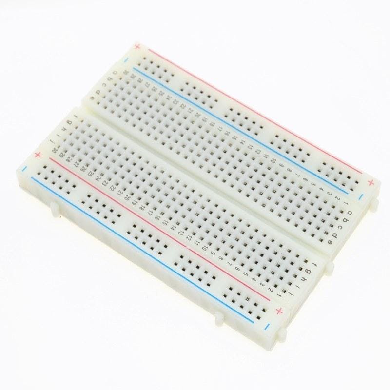
面包板
Visuino 程序:下载 Visuino
第 2 步:威廉希尔官方网站
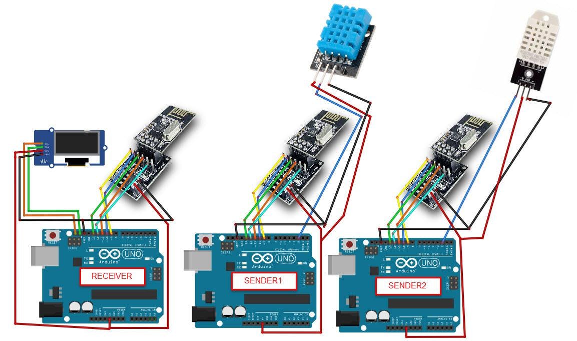
对于这个项目,我们使用 NRF24L01 模块和电压适配器。
连接发送器 1 Arduino:
将 NRF24L01 适配器引脚 [VCC] 连接到 Arduino 引脚 [5V]
将 NRF24L01 适配器引脚 [GND] 连接到 Arduino 引脚 [GND]
将 NRF24L01 适配器引脚“芯片启用”[CE] 连接到 Arduino 数字引脚 [9]
将 NRF24L01 适配器引脚“芯片选择”[CSN] 连接到 Arduino 数字引脚 [10]
将 NRF24L01 适配器引脚 [SCK] 连接到 Arduino 数字引脚 [13]
将 NRF24L01 适配器引脚 [MO] 连接到 Arduino 数字引脚 [11]
将 NRF24L01 适配器引脚 [MI] 连接到 Arduino 数字引脚 [12]
将 DHT11 传感器引脚 [VCC] 连接到 Arduino 引脚 [5V]
将 DHT11 传感器引脚 [GND] 连接到 Arduino 引脚 [GND]
将 DHT11 传感器引脚 [OUT] 连接到 Arduino 数字引脚 [2]
连接发送器 2 Arduino:
将 NRF24L01 适配器引脚 [VCC] 连接到 Arduino 引脚 [5V]
将 NRF24L01 适配器引脚 [GND] 连接到 Arduino 引脚 [GND]
将 NRF24L01 适配器引脚“芯片启用”[CE] 连接到 Arduino 数字引脚 [9]
将 NRF24L01 适配器引脚“芯片选择”[CSN] 连接到 Arduino 数字引脚 [10]
将 NRF24L01 适配器引脚 [SCK] 连接到 Arduino 数字引脚 [13]
将 NRF24L01 适配器引脚 [MO] 连接到 Arduino 数字引脚 [11]
将 NRF24L01 适配器引脚 [MI] 连接到 Arduino 数字引脚 [12]
将 DHT22 传感器引脚 [VCC] 连接到 Arduino 引脚 [5V]
将 DHT22 传感器引脚 [GND] 连接到 Arduino 引脚 [GND]
将 DHT22 传感器引脚 [OUT] 连接到 Arduino 数字引脚 [2]
连接接收器 Arduino:
将 NRF24L01 适配器引脚 [VCC] 连接到 Arduino 引脚 [5V]
将 NRF24L01 适配器引脚 [GND] 连接到 Arduino 引脚 [GND]
将 NRF24L01 适配器引脚“芯片启用”[CE] 连接到 Arduino 数字引脚 [9]
将 NRF24L01 适配器引脚“芯片选择”[CSN] 连接到 Arduino 数字引脚 [10]
将 NRF24L01 适配器引脚 [SCK] 连接到 Arduino 数字引脚 [13]
将 NRF24L01 适配器引脚 [MO] 连接到 Arduino 数字引脚 [11]
将 NRF24L01 适配器引脚 [MI] 连接到 Arduino 数字引脚 [12]
将 OLED 显示引脚 [SCL] 连接到 Arduino 引脚 [SCL]
将 OLED 显示引脚 [SDA] 连接到 Arduino 引脚 [SDA]
将 OLED 显示引脚 [VCC] 连接到 Arduino 引脚 [5v]
将 OLED 显示引脚 [GND] 连接到 Arduino 引脚 [GND]
第 3 步:启动 Visuino,并选择 Arduino UNO 板类型
1 / 2
Visuino:https ://www.visuino.eu也需要安装。下载免费版本或注册免费试用。
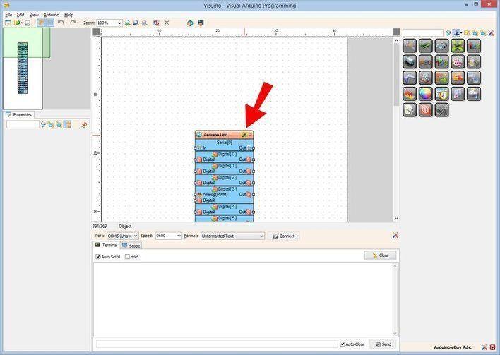
如图1所示启动Visuino 单击Visuino中Arduino组件(图1)上的“工具”按钮 出现对话框时,选择“Arduino UNO”,如图2所示
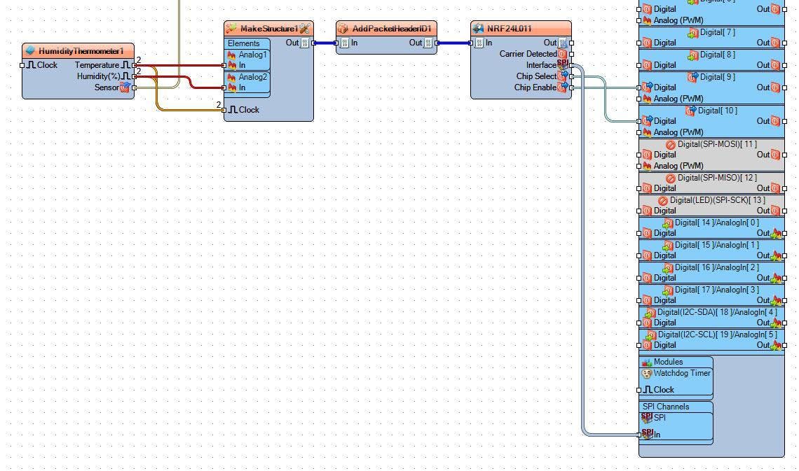
第 4 步:对于 Sender1 Arduino - 在 Visuino 中添加、设置和连接组件
1 / 8
添加“制作结构”组件
添加“ NRF24L01 ”组件
添加“添加包头ID ”组件
添加“ DHT ”组件
双击“ MakeStructure1 ”并在“ Elements ”窗口中将 2X“ Analog ”拖到左侧并关闭“Elements”窗口
关闭“元素”窗口
选择“ HumidityThermometer1 ”并在属性中将“类型”设置为您使用的传感器,DHT11、DHT22 等
选择“ AddPacketHeaderID1 ”并在属性窗口中选择“ ID ”并单击“3 Dots”按钮并在“ ID ”窗口中设置一个唯一的字节序列作为 ID,例如34 67 (见图)
关闭“ ID ”窗口
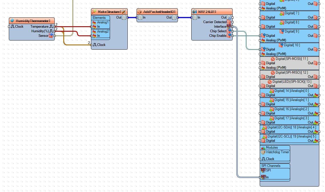
将“ HumidityThermometer1 ”引脚 [Temperature] 连接到“ MakeStructure1 ”>“ Analog1 ”引脚 [In]
将“ HumidityThermometer1 ”引脚 [Temperature] 连接到“ MakeStructure1 ”引脚 [Clock]
将“ HumidityThermometer1 ”引脚[湿度]连接到“ MakeStructure1 ”>“ Analog2 ”引脚[In]
将“ HumidityThermometer1 ”引脚[湿度]连接到“ MakeStructure1 ”引脚[时钟]
将“ HumidityThermometer1 ”引脚 [Sensor] 连接到Arduino数字引脚 [2]
将“ NRF24L011 ”引脚接口 [SPI] 连接到Arduino板引脚 [SPI]
将“ NRF24L011 ”引脚[芯片选择]连接到Arduino板数字引脚[10]
将“ NRF24L011 ”引脚[芯片启用]连接到Arduino板数字引脚[9]
将“ MakeStructure1 ”引脚 [Out] 连接到“ AddPacketHeaderID1 ”引脚 [In]
将“ AddPacketHeaderID1 ”引脚 [Out] 连接到“ NRF24L011 ”引脚 [In]
将项目上传到 Arduino 板(请参阅生成、编译和上传 Arduino 代码步骤)
第 5 步:对于 Sender2 Arduino - 在 Visuino 中添加、设置和连接组件
1 / 8
添加“制作结构”组件
添加“ NRF24L01 ”组件
添加“添加包头ID ”组件
添加“ DHT ”组件
双击“ MakeStructure1 ”并在“ Elements ”窗口中将 2X“ Analog ”拖到左侧并关闭“Elements”窗口
关闭“元素”窗口
选择“ HumidityThermometer1 ”并在属性中将“类型”设置为您使用的传感器,DHT11、DHT22 等
选择“ AddPacketHeaderID1 ”并在属性窗口中选择“ ID ”并单击“3 Dots”按钮并在“ ID ”窗口中设置一个唯一的字节序列作为 ID,例如34 21 (见图)
关闭“ ID ”窗口
将“ HumidityThermometer1 ”引脚 [Temperature] 连接到“ MakeStructure1 ”>“ Analog1 ”引脚 [In]
将“ HumidityThermometer1 ”引脚 [Temperature] 连接到“ MakeStructure1 ”引脚 [Clock]
将“ HumidityThermometer1 ”引脚[湿度]连接到“ MakeStructure1 ”>“ Analog2 ”引脚[In]
将“ HumidityThermometer1 ”引脚[湿度]连接到“ MakeStructure1 ”引脚[时钟]
将“ HumidityThermometer1 ”引脚 [Sensor] 连接到Arduino数字引脚 [2]
将“ NRF24L011 ”引脚接口 [SPI] 连接到Arduino板引脚 [SPI]
将“ NRF24L011 ”引脚[芯片选择]连接到Arduino板数字引脚[10]
将“ NRF24L011 ”引脚[芯片启用]连接到Arduino板数字引脚[9]
将“ MakeStructure1 ”引脚 [Out] 连接到“ AddPacketHeaderID1 ”引脚 [In]
将“ AddPacketHeaderID1 ”引脚 [Out] 连接到“ NRF24L011 ”引脚 [In]
将项目上传到 Arduino 板(请参阅生成、编译和上传 Arduino 代码步骤)
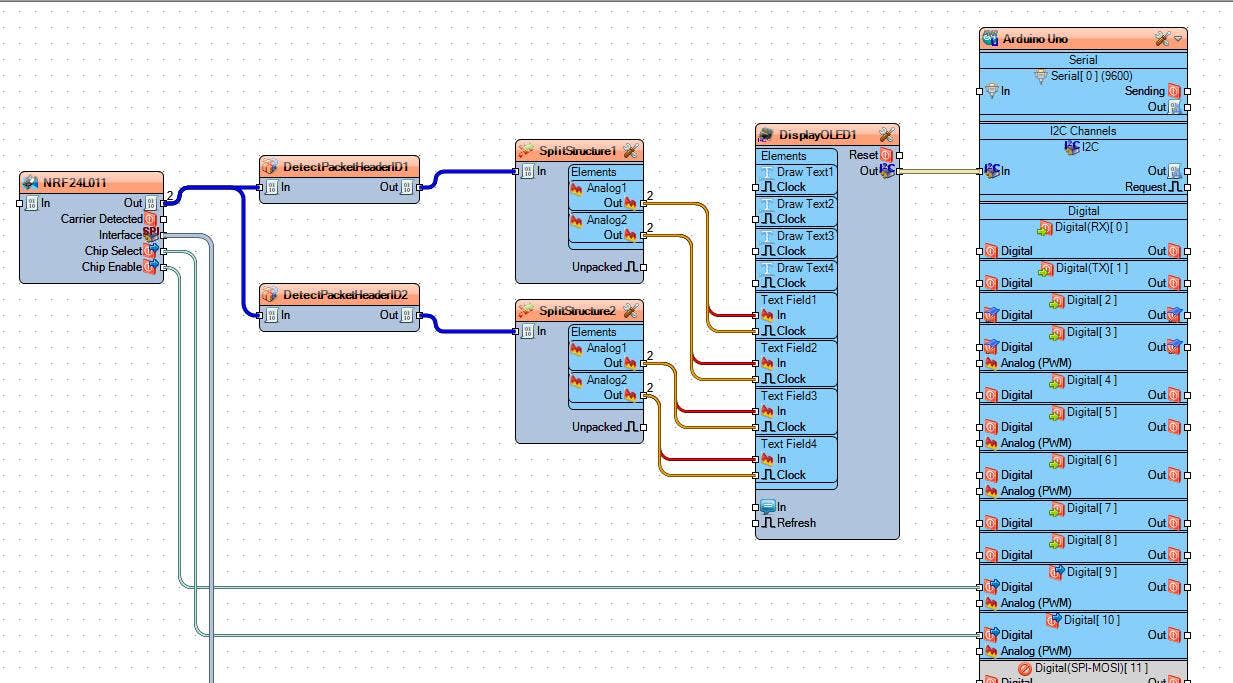
第 6 步:对于接收器 Arduino - 在 Visuino 中添加、设置和连接组件
1 / 18
添加“ OLED I2C ”组件
添加“ NRF24L01 ”组件
添加 2X“拆分结构”组件
添加 2X“ Detect Packet Header ID ”组件
选择“DetectPacketHeaderID1”并在属性窗口中选择“ ID ”并单击 3 Dots 按钮并在“ ID ”窗口中设置您为 Sender1 设置的唯一字节序列,例如34 67 (见图)
关闭“ ID ”窗口
选择“DetectPacketHeaderID2”并在属性窗口中选择“ ID ”并单击 3 Dots 按钮并在“ ID ”窗口中设置您为 Sender2 设置的唯一字节序列,例如34 21 (见图)
关闭“ ID ”窗口
双击“ SplitStructure1 ”并在“Elements”窗口中将 2x“ Analog ”拖到左侧
关闭“元素”窗口
双击“ SplitStructure2 ”并在“Elements”窗口中将 2x“ Analog ”拖到左侧
关闭“元素”窗口
双击“DisplayOLED1”,在 Elements 窗口中将 4X“ Text Field ”和 4X“ Draw Text ”拖到左侧
选择“ Draw Text1 ”并在属性窗口中将“ Text ”设置为 Sender1,将“ X ”设置为 30
选择“ Draw Text2 ”并在属性窗口中将“ Text ”设置为 Sender2,将“ X ”设置为 85
选择“ Draw Text3 ”并在属性窗口中将“ Text ”设置为 TEMP:并将“ Y ”设置为 20
选择“ Draw Text4 ”并在属性窗口中将“ Text ”设置为 HUM: 并将“ Y ”设置为 40
选择“ Text Field1 ”并在属性窗口中将“ X ”设置为 50,将“ Y ”设置为 20
选择“ Text Field2 ”并在属性窗口中将“ X ”设置为 50,将“ Y ”设置为 40
选择“ Text Field3 ”并在属性窗口中将“ X ”设置为 90,将“ Y ”设置为 20
选择“ Text Field4 ”并在属性窗口中将“ X ”设置为 90,将“ Y ”设置为 40
关闭“元素”窗口
将“ NRF24L011 ”引脚接口 [SPI] 连接到Arduino板引脚 [SPI]
将“ NRF24L011 ”引脚 [Chip Select] 连接到 Arduino 板数字引脚 [10]
将“ NRF24L011 ”引脚[芯片启用]连接到Arduino板数字引脚[9]
将“ NRF24L011 ”引脚 [Out] 连接到“DetectPacketHeaderID1”引脚 [In]
将“ NRF24L011 ”引脚 [Out] 连接到“DetectPacketHeaderID2”引脚 [In]
将“ DetectPacketHeaderID1 ”引脚 [Out] 连接到“ SplitStructure1 ”引脚 [In]
将“ DetectPacketHeaderID2 ”引脚 [Out] 连接到“ SplitStructure2 ”引脚 [In]
将“ SplitStructure1 ”>“ Analog1 ”引脚 [Out] 连接到“ DisplayOLED1 ”>“ Text Field1 ”引脚 [In] 和引脚 [Clock]
将“ SplitStructure1 ”>“ Analog2 ”引脚 [Out] 连接到“ DisplayOLED1 ”>“ Text Field2 ”引脚 [In] 和引脚 [Clock]
将“ SplitStructure2 ”>“ Analog1 ”引脚 [Out] 连接到“ DisplayOLED1 ”>“ Text Field3 ”引脚 [In] 和引脚 [Clock]
将“ SplitStructure2 ”>“ Analog2 ”引脚[Out]连接到“ DisplayOLED1 ”>“ Text Field4 ”引脚[In]和引脚[Clock]
将“ DisplayOLED1 ”引脚 [I2C] 连接到Arduino引脚 [I2C]
第 7 步:生成、编译和上传 Arduino 代码

在 Visuino 中,点击底部的“ Build ”选项卡,确保选择了正确的端口,然后点击“ Compile/Build and Upload ”按钮。
第 8 步:播放
如果为 Arduino 模块供电,连接到接收器Arduino 的 OLED 显示器将开始显示来自第一个发送器的温度和湿度以及从第二个发送器Arduino 接收到的温度和湿度。
恭喜!您已经使用 Visuino 完成了您的项目。还附上了我为本教程创建的发送方和接收方的 Visuino 项目文件,您可以下载它并在 Visuino 中打开它:https ://www.visuino.eu
声明:本文内容及配图由入驻作者撰写或者入驻合作网站授权转载。文章观点仅代表作者本人,不代表电子发烧友网立场。文章及其配图仅供工程师学习之用,如有内容侵权或者其他违规问题,请联系本站处理。 举报投诉
- 相关下载
- 相关文章


