
奇偶校验器的设计方法和特点
描述

奇偶校验是一种简单、实现代价小的检错方式,常用在数据传输过程中。对于一组并行传输的数据(通常为8比特),可以计算岀它们的奇偶校验位并与其一起传输。接收端根据接收的数据重新计算其奇偶校验位并与接收的值进行比较,如果二者不匹配,那么可以确定数据传输过程中岀现了错误;如果二者匹配,可以确定传输过程中没有出错或者出现了偶数个错误(出现这种情况的概率极低)。
需要指出当出现偶数个错误时,奇偶校验是无法检测此时威廉希尔官方网站 出现传输错误。例如,发送的数据为8’b1010_1011此时计算出的偶校验值是1。如果在传输中后两位从11跳变为00,那么此时接收到的数据为8’b10100100,接收的偶校验值仍然为1。对接收的数据进行偶校验计算,得到的结果仍然为1,这与收到的校验值是相同的,接收威廉希尔官方网站 无法检测出接收数据中岀现的错误。
奇偶校验位有两种类型:偶校验位与奇校验位。
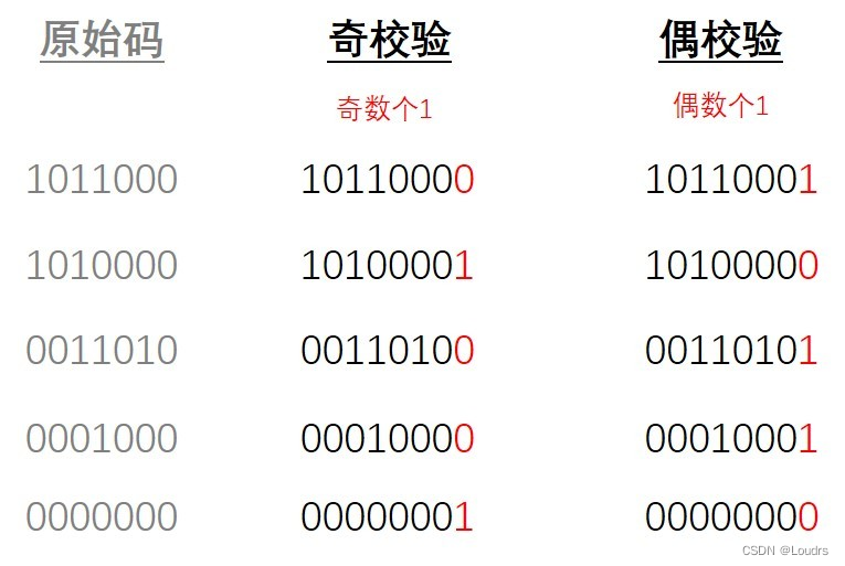
以偶校验位来说,如果一组给定数据位中1的个数是奇数,补一个bit为1,使得总的1的个数是偶数。例:0000001, 补一个bit为1, 00000011。
以奇校验位来说,如果给定一组数据位中1的个数是奇数,补一个bit为0,使得总的1的个数是奇数。例:0000001, 补一个bit为0, 00000010。

简单理解奇偶校验:
奇校验:原始码流+校验位 总共有奇数个1
偶校验:原始码流+校验位 总共有偶数个1
二、XOR法
2.1 XOR法
题目:采用XOR法试写一个发送端奇偶校验器,在发送端会输入一段8bit的数据,可以选择切换奇数校验或者偶数校验,并且将校验值附在末位输出。
2.2 verilog代码
//使用XOR法设计奇偶校验器
module parity_checker01(
input clk,
input rst_n,
input parity_odd,//是否为奇校验:奇数校验为1,偶数校验位0
input [7:0] data_in,//输入的八位数据
output [8:0] data_out,//输出的九位数据
output reg even_bit,//偶数校验码
output reg odd_bit//计数校验码
);
//使用按位异或确定偶数校验码和奇数校验码
always@(posedge clk or negedge rst_n) begin
if(!rst_n) begin
even_bit <= 1'b0;
odd_bit <= 1'b0;
end
else begin
even_bit <= ^data_in; //偶校验条件下计算出来的校验位
odd_bit <= ~(^data_in);//奇校验条件下计算出来的校验位
end
end
//组合逻辑完成输入数据与校验码的拼接
assign data_out = parity_odd ? {data_in[7:0],odd_bit}
: {data_in[7:0],even_bit};
endmodule
2.3 Testbench
`timescale 1ns / 1ps//仿真时间单位1ns 仿真时间精度1ps
module parity_checker01_tb();
//信号申明
regclk;
regrst_n;
reg parity_odd;
reg [7:0] data_in;
wire [8:0] data_out;
wire even_bit;
wire odd_bit;
//模块实例化(将申明的信号连接起来即可)
parity_checker01 u_parity_checker01(
.clk (clk),
.rst_n (rst_n),
.parity_odd (parity_odd),
.data_in (data_in),
.data_out (data_out),
.even_bit (even_bit),
.odd_bit (odd_bit)
);
//生成时钟信号
always #5 clk = ~clk;
//生成复位信号
//为时钟信号和复位信号等赋初值
initial begin
clk = 1;
rst_n = 1;
data_in = 0;
parity_odd = 1;
#5 rst_n <= 0;
#5 rst_n <= 1;
data_in = 8'h01;
#20
data_in = 8'hb7;
#20
data_in = 8'h32;
#20
data_in = 8'he9;
#20
data_in = 8'hd3;
end
endmodule
2.4 仿真结果

三、计数器法
3.1 计数器法
题目:采用计数器法试写一个发送端奇偶校验器,在发送端会输入一段8bit的数据,可以选择切换奇数校验或者偶数校验,并且将校验值附在末位输出。
3.2 verilog代码
//使用计数器法设计奇偶校验器
module parity_checker02(
input clk,
input rst_n,
input parity_odd,//是否为奇校验:奇数校验为1,偶数校验位0
input [7:0] data_in,//输入的八位数据
output [8:0] data_out,//输出的九位数据
output reg even_bit,//偶数校验码
output reg odd_bit//奇数校验码
);
//定义一个三位宽的计数器
reg[2:0] cnt;
//计数器模块
//输入数据data_in逢1逐位计数
integer i;
always @(*) begin
cnt = 3'd0;
for (i=0;i<8;i=i+1) begin
if(data_in[i]==1'b1) begin
cnt = cnt + 1;
end
end
end
//计数器校验模块
//使用时序逻辑对计数器中的1校验奇数or偶数
//计数器最低位为奇数,则整体为奇数,反之为偶数
always@(posedge clk or negedge rst_n) begin
if(!rst_n) begin
even_bit <= 1'b0;
odd_bit <= 1'b0;
end
else if(cnt[0] == 1'b1) begin//通过计数器最低位判断是否为偶数
even_bit <= 1'b1;
odd_bit <= 1'b0;
end
else begin
even_bit <= 1'b0;
odd_bit <= 1'b1;
end
end
//组合逻辑完成输入数据与校验码的拼接
assign data_out = parity_odd ? {data_in[7:0],odd_bit}
: {data_in[7:0],even_bit};
endmodule
3.3 Testbench
`timescale 1ns / 1ps//仿真时间单位1ns 仿真时间精度1ps
module parity_checker02_tb();
//信号申明
regclk;
regrst_n;
reg parity_odd;
reg [7:0] data_in;
wire [8:0] data_out;
wire even_bit;
wire odd_bit;
//模块实例化(将申明的信号连接起来即可)
parity_checker02 u_parity_checker02(
.clk (clk),
.rst_n (rst_n),
.parity_odd (parity_odd),
.data_in (data_in),
.data_out (data_out),
.even_bit (even_bit),
.odd_bit (odd_bit)
);
//生成时钟信号
always #5 clk = ~clk;
//生成复位信号
//为时钟信号和复位信号等赋初值
initial begin
clk = 1;
rst_n = 1;
data_in = 0;
parity_odd = 1;
#5 rst_n <= 0;
#5 rst_n <= 1;
data_in = 8'h01;
#10
data_in = 8'hb7;
#10
data_in = 8'h32;
#10
data_in = 8'he9;
#10
data_in = 8'hd3;
end
endmodule
仿真结果

四、总结
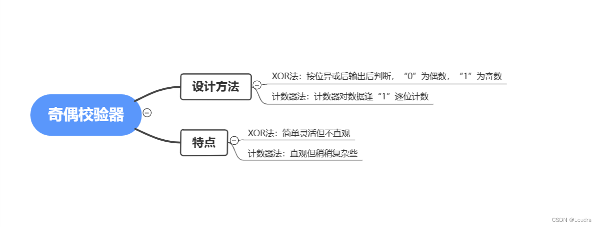
奇偶校验器设计主要思路是通过弄清一组数据中“1”和“0”的数目。若是奇校验则原始码流+校验位总共有奇数个“1”;若是偶校验则原始码流+校验位总共有偶数个“1”。设计方法主要有XOR法和计数器法。XOR法最简单,只需要对数据使用按位异或,输出为“0”代表数据中“1”位偶数个;计数器法最直观,计数器中数值的奇偶性表示对应数据中“1”个数的奇偶。
Tips:判断计数器是奇数还是偶数主要有判断data_out[0]和取余数两种方法,前者综合后耗损的资源太多不推荐前者。
审核编辑:汤梓红
-
串口调试助手的奇偶校验测试方法2015-04-28 0
-
UART中有奇偶校验位和无奇偶校验位的数据传输是怎样的?2022-12-08 0
-
奇偶校验码2009-10-13 5349
-
奇偶校验器,奇偶校验器是什么意思2010-03-08 2221
-
奇偶校验码,奇偶校验码原理是什么?2010-03-17 62751
-
奇偶校验器_奇偶校验设计程序2011-11-11 5723
-
stm32串口奇偶校验2021-07-23 11179
-
stm32 usart奇偶校验如何配置2021-07-23 7561
-
STM32的UART奇偶校验注意2021-12-28 1415
-
增强FIFO模式下的奇偶校验2022-11-02 1048
-
FPGA奇偶校验的基本原理及实现方法2023-05-14 3043
-
什么是奇偶校验 奇偶校验的基本原理 奇偶校验威廉希尔官方网站 什么意思2023-10-17 3723
-
什么是奇偶校验威廉希尔官方网站 ?奇偶校验器是时序逻辑威廉希尔官方网站 吗?2023-10-17 3648
-
什么是奇校验和偶校验?常见的奇偶校验方式有哪些?2023-10-17 10348
-
奇偶校验和crc校验的区别 CRC校验和奇偶校验之间有什么关系?2023-10-17 3401
全部0条评论

快来发表一下你的评论吧 !

