

RZ/T2M RZ/N2L RZ/T2L系列应用心得(下)
描述
九CN032套件中的新功率板的连接方式说明
老版本功率板:
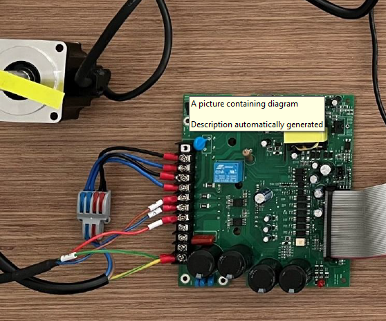
新版本功率板:
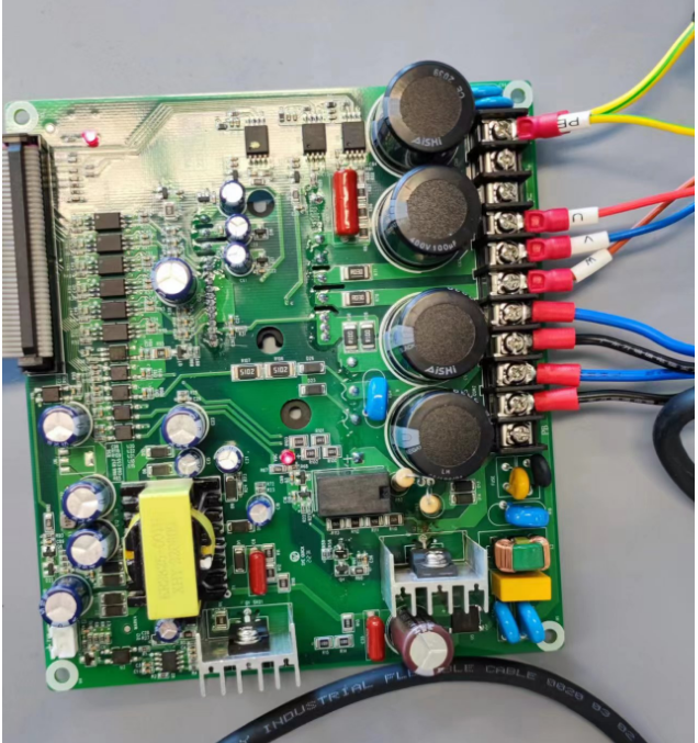
差别
新的版本从PE保护地起,中间是2个接线柱,老版本是3个,注意千万不要按照老的接线方式,会炸管子。
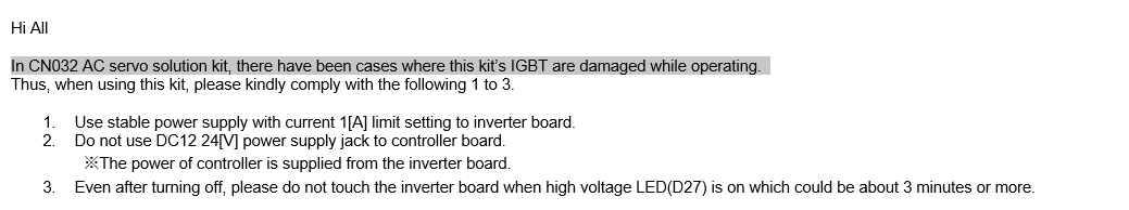
另外,请注意
1220V限制1A
2逆变板供电时候不要接DC电源到主控制板
3下电后放电彻底后再操作
十IAR新工程的创建示例
请参考百度网盘与客户的培训视频
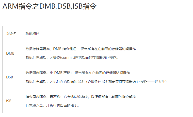
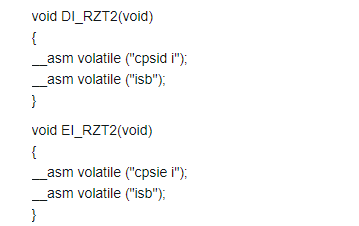
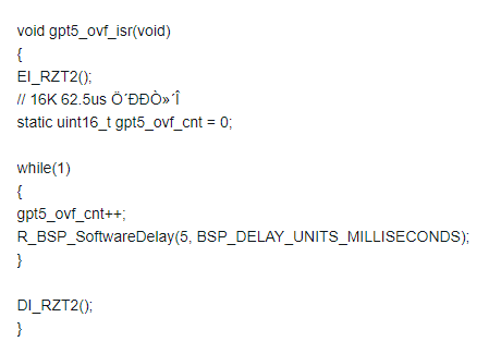
十一如何开启中断嵌套
在中断函数进入后插入
__asm volatile ("cpsie i");//打开全局中断
__asm volatile ("isb");//同步指令
出中断处插入关闭中断
__asm volatile ("cpsid i");//
__asm volatile ("isb");//同步指令
示例
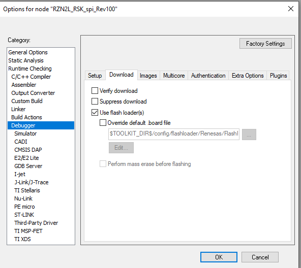
十二EVK xSPI0 IAR编译及烧写程序说明
1CN8接2-3,接通QSPI的电源
2Smart configurator选择xspi0启动
3Debugger可以选择I-jet或者J-Link
4I-jet需配置如下
5断点设置如下
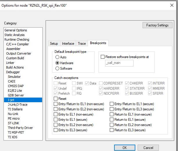
如使用J-Link也使用硬件断点
如出现类似如下错误报警:xspi0地址区域验证错误
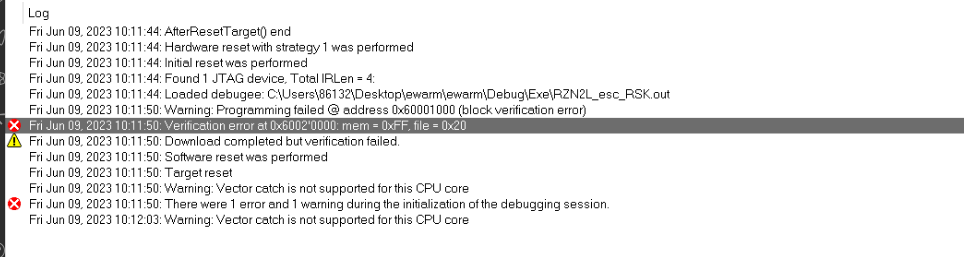
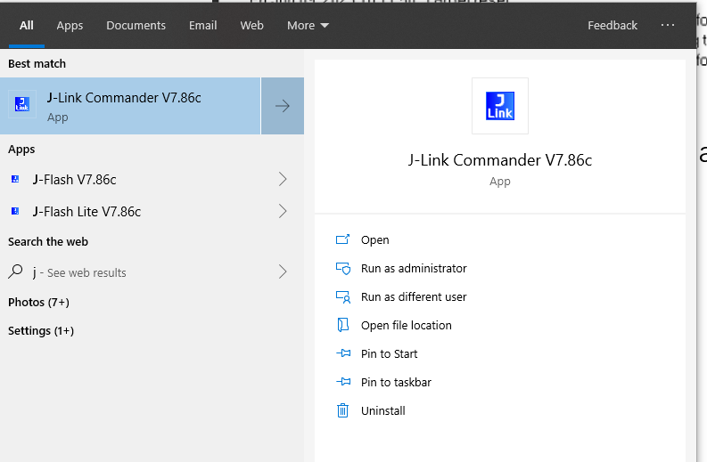
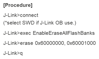
需使用J-Link commander擦除qspi flash
十三USB PCDC例程如何判断上位机串口调试助手连接成功
如下部分代码加在
case USB_STATUS_REQUEST: /* Receive Class Request */
里
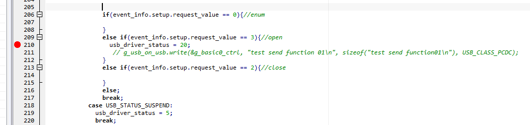
==3代表上位机串口软件打开,可以进行数据收发。
十四关于N2L 225pin封装
1可以直接使用CN032的主板封装(autium designer格式)
2参考datasheet时候,其视图为底视图,即球面对人

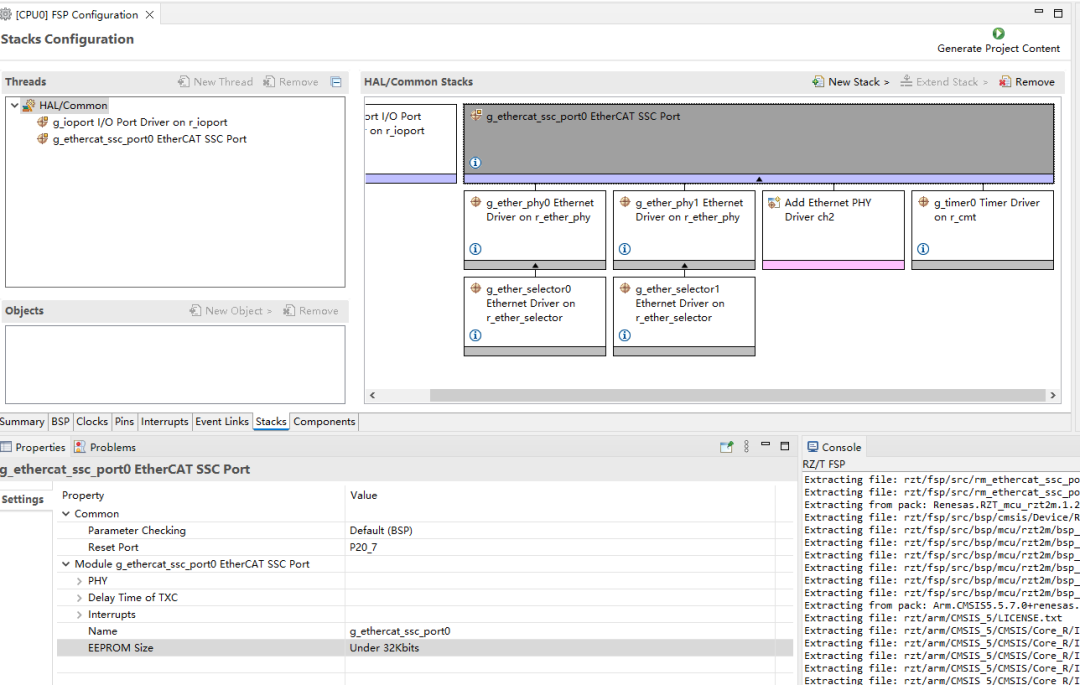
十五RSK版EEPROM TWinCAT更新不进去解决方法
把eeprom size改成与RSK板子对照
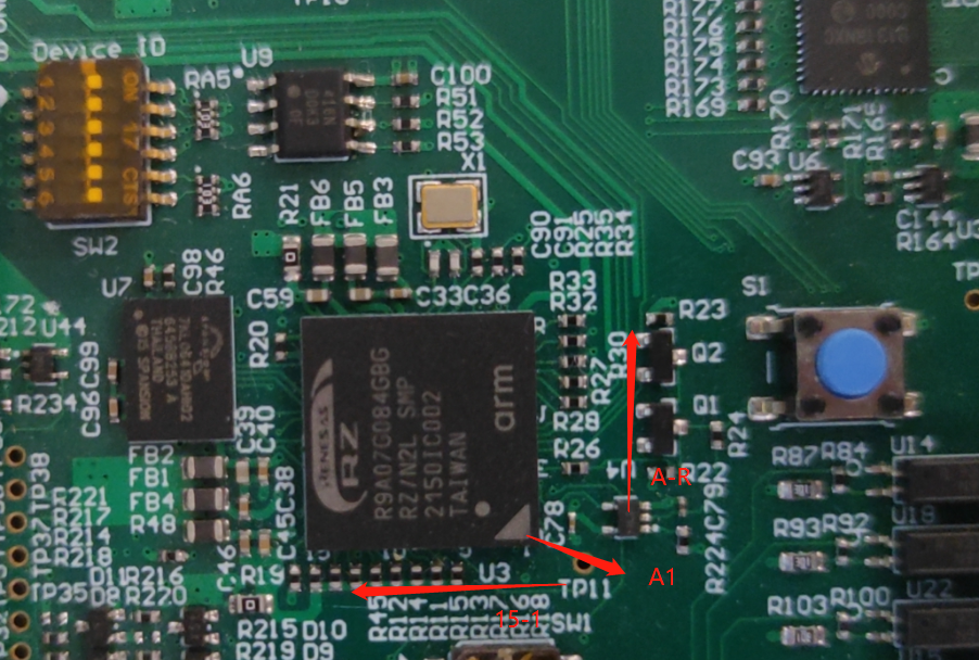
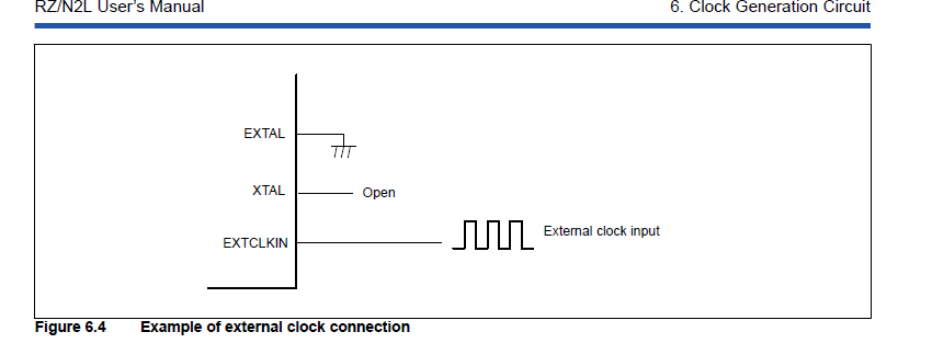
十六外部晶振推荐使用有源晶振
十七
P17_5 使用注意
初始状态是RSTOUT配置,不要用做Digital output.
十八SDRAM使用注意
使用CS2. CS3不能单独使用
十九EIP例程测试
需要下载CODESYS version 3.5.15.10 32-bit,因为例程和这个版本适配,其他版本不行。
CODESYS Development System V3

下载前需要先注册codesys会员,免费。
二十T2M N2L电流环运行时间测试
可以在CN032套件上测试,在电流环运行前后增加GPIO翻转,然后去除掉反转时间就是电流环运行时间:
下图上面是T2M下面是N2L,基于瑞萨的电流环算法。
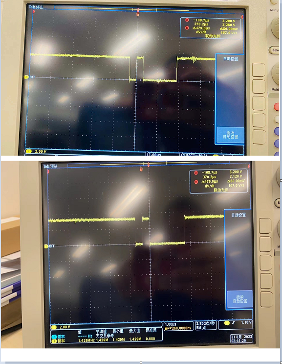
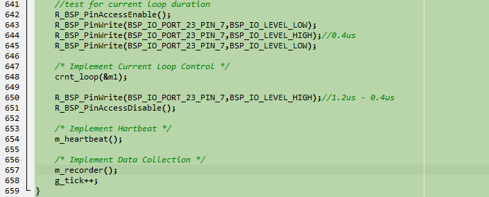
从图上看,T2M电流环大约1us N2L 1.35us.
二十一Freertos使用指导
使用freertos和多个不同优先级中断时候,需要修改如下内容:
1Target File: port.c
左右滑动查看完整内容
void vApplicationIRQHandler (uint32_t ulICCIAR)
{
  #if 0
    /* Re-enable interrupts. */
    __asm("cpsie i");
  #endif
  bsp_common_interrupt_handler(ulICCIAR);
}
2Target File: bsp_irq.c
左右滑动查看完整内容
void bsp_common_interrupt_handler (uint32_t id)
{
  uint16_t gic_intid;
  /* Get interruot ID (GIC INTID). */
  gic_intid = (uint16_t) (id & BSP_PRV_ID_MASK);
#if  VECTOR_DATA_IRQ_COUNT > 0
  if (BSP_CORTEX_VECTOR_TABLE_ENTRIES <= gic_intid)
  {
    /* Remain the interrupt number */
    g_current_interrupt_num[g_current_interrupt_pointer++] =
    (uint16_t) (gic_intid - BSP_CORTEX_VECTOR_TABLE_ENTRIES);
    __asm volatile ("dmb");
    #if 1
      /* Enable nested interrupt. */
      __asm volatile ("cpsie i");
      __asm volatile ("isb");
      #endif
      /* Branch to an interrupt handler. */
      g_vector_table[(gic_intid - BSP_CORTEX_VECTOR_TABLE_ENTRIES)]();
      }
      else
    #endif
{
/* Remain the interrupt number */
g_current_interrupt_num[g_current_interrupt_pointer++] = gic_intid;
__asm volatile ("dmb");
#if 1
/* Enable nested interrupt. */
__asm volatile ("cpsie i");
__asm volatile ("isb");
#endif
/* Branch to an interrupt handler. */
g_sgi_ppi_vector_table[gic_intid]();
}
#if 1
/* Disable nested interrupt. */
__asm volatile ("cpsid i");
__asm volatile ("isb");
#endif
g_current_interrupt_pointer--;
}
二十二FSP更改设置后编译报错
bsp_mcu_device_pn_cfg.h :No such file or direction
问题一般发生在
Changed from RSK+RZN2L (RAM execution without flash memory) to RZN2L Custom User Board (xSPI0 x1 boot mode)
bsp_mcu_device_pn_cfg.h 没有自动生成,所以报错:
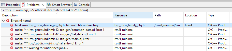
Workaround:
Please create a new project to change the board setting to RZN2L Custom User Board.
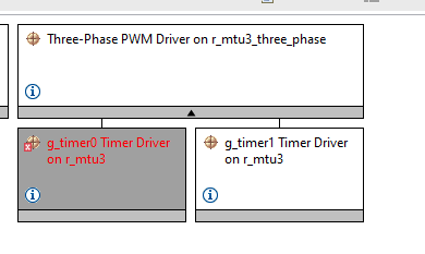
二十三MTU3定时器中断进不去中断问题(FSP V1.2以下版本,1.2和以上无问题)
1增加三相电机驱动
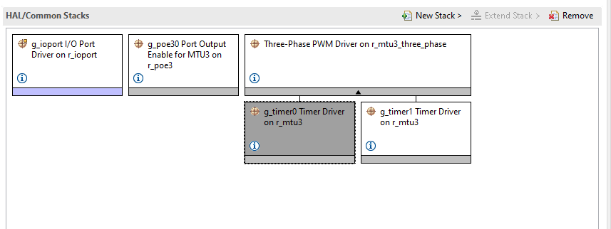
2配置定时器中断(定时器比较匹配中断,一般在这个中断里更新pwm duty cycle)
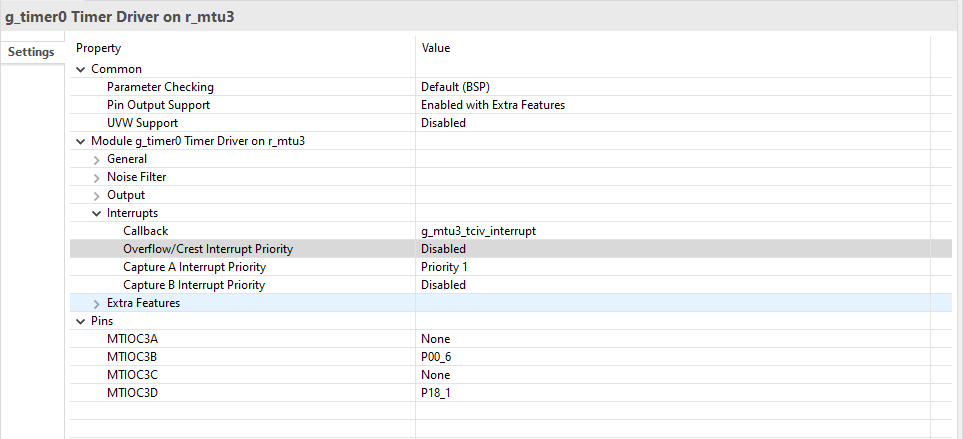
此时不用管报错:
直接点生成代码

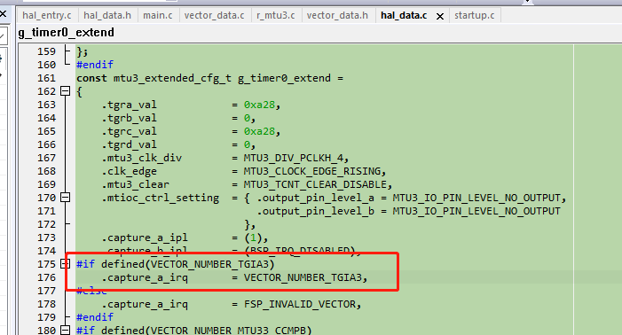
3修改如下生成的文件
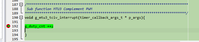
4增加中断回调函数
5举一反三,如果其他定时器中断进不去,也可以查查是不是hal_data.c里面生成的代码中断向量号这里宏定义出错了。
二十四串口引脚使用注意
串口引脚最好定义在P16 P18这两组引脚上,因为这两组支持ELC,可以方便的去做不定长数据的接收。
审核编辑:汤梓红
-
RZ/T2M、RZ/N2L 组硬件设计指南2023-01-09 376
-
RZ/T2M 组 RZ/T2M Motor Solution Kit Startup 手册(for RZ/T2M Motion Control Utility)2023-01-10 329
-
RZ/T2M 组 RZ/T2M Motor Solution Board 硬件手册2023-01-10 269
-
CN032交流伺服解决方案硬件手册(适用于RZ/T2M、RZ/N2L)2023-05-12 256
-
RZ/T2L 组用户手册:硬件2023-06-29 278
-
RZ/T2M、RZ/N2L和RZ/T2L产品简介2023-11-13 2915
-
RZ/T2M RZ/N2L RZ/T2L系列应用心得2023-11-15 2317
-
RZ/T2M RZ/N2L RZ/T2L系列应用心得(上)2023-12-29 2559
-
RZ/T2M、RZ/N2L、RZ/T2L组 硬件设计指南2024-02-02 295
-
瑞萨教你如何使用RZ/T2L RZ/N2L RSK J-Link OB2024-05-07 1966
-
RZ/T2M, RZ/T2L, RZ/N2L电机解决方案套件数据手册2024-05-13 418
全部0条评论

快来发表一下你的评论吧 !
