

智能杯垫:基于Seed Studio XIAO SAMD21的温度监测系统
描述
今天为大家带来的是来自创作者Gokux的作品: 温度监测智能杯垫.这个装置可以实时监控和显示放置在其上的饮料温度,帮助用户避免饮用过热或过冷的饮料。
项目背景
喝茶咖啡等饮品时,一个合适的温度对饮用者而言至关重要。饮品过热容易烫嘴,过冷又失去其口感与味道。因此,设计并构建一个智能杯垫,可以实时监控和显示放置在其上的饮料温度,帮助用户避免饮用过热或过冷的饮料。
我们使用红外温度传感器GY-906 MLX90614来感知温度。结果将显示在一个小的OLED屏幕上。所有这些组件都由seed Studio XIAO SAMD21控制。这个项目的大部分都是使用3D打印技术创建的。
所需材料
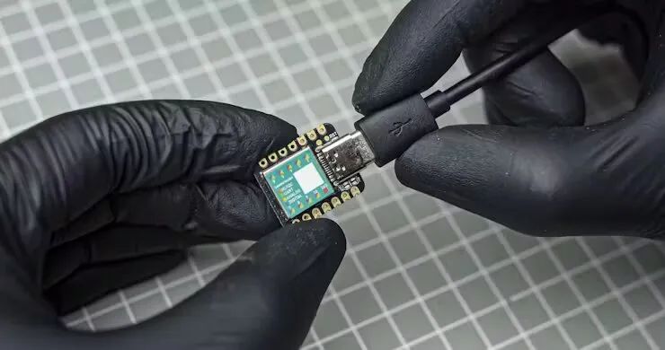
Seeed Studio XIAO SAMD21
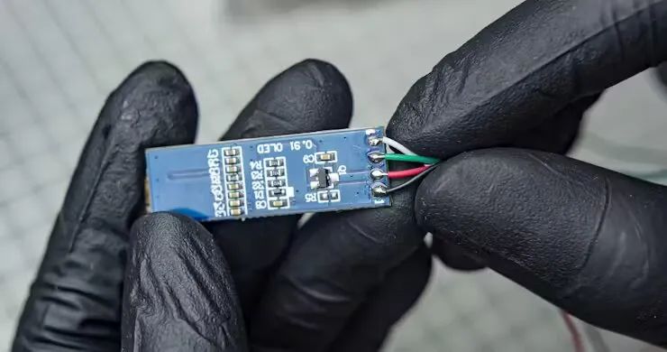
0.91英寸 128×32 OLED LCD显示屏
红外温度传感器GY-906 MLX90614
6*CSK Allen M3 x 10mm
30Awg连接线
哑光黑色喷漆
120格砂纸
3D打印机
胶枪
焊接套件
外观准备
建模:
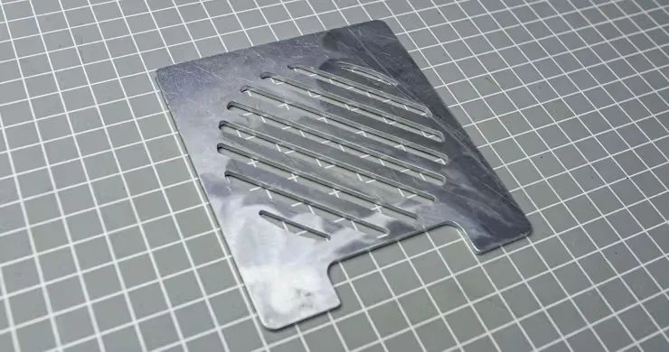
外观通过使用Fusion 360进行规划和设计,在完成该设计的完整3D模型后,我仅提取了铝制部分以便于操作。我在键盘上按下“P”键进行投影映射,并选择了前面板。这将把前面板投影到一个新的草图中。切换到草图标签,找到投影的草图。右键单击该草图,选择“另存为DXF”。然后选择在您的PC上保存的位置。找到可以访问到您所在地区的在线或离线激光切割服务。
back_plate_zvwAVyCTKC.stlmain_body_cFgRrmUCTW.stlsensor_back_plate_wpGXR0ySTf.stlsensor_holder_V48rjvjxqT.stl
准备顶板:
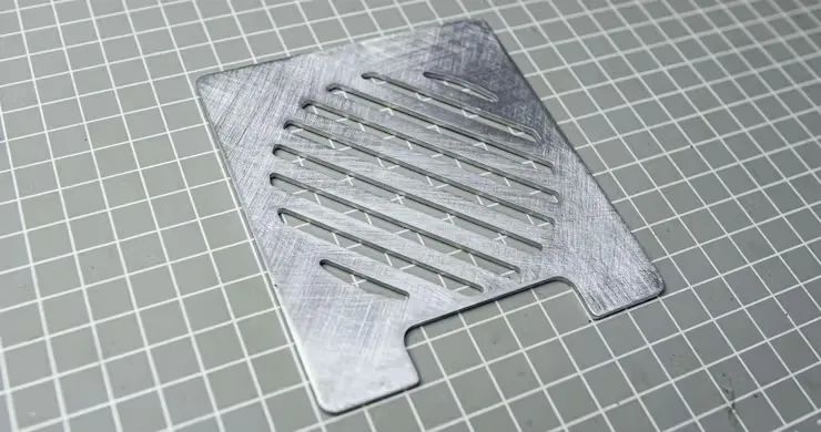
收到铝制部分后,我们使用120格砂纸稍微打磨两面。
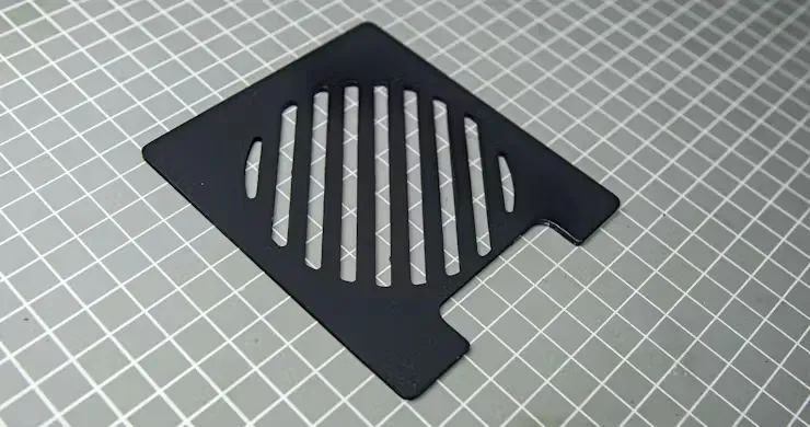
打磨后我们需要喷漆2层,然后晾干
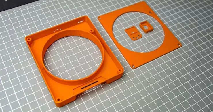
3D 打印零件:我们还需要为这个项目3D打印一些零件。我们使用3D打印机打印上面设计的stl文件。
代码部分
在将部件进行组装之前,我们先编写代码,并且通过Arduino IDE将代码烧录到Seeed Studio XIAO SAMD21中,具体代码如下:
#include
组装与接线
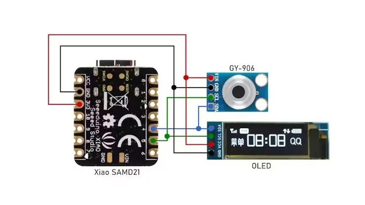
● D4 of xiao to SDA of OLED and GY-906
● D5 of xiao to SCL of OLED and GY-906
● 3v3 of xiao to VCC of OLED AND GY-906
● GND of xiao to GND of OLED and GY-906
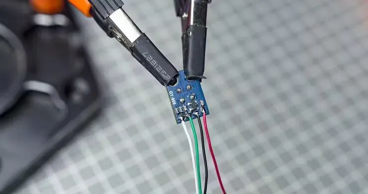
我们先从传感器安装组件开始:1、 将四根8厘米的电线焊接到GY-906
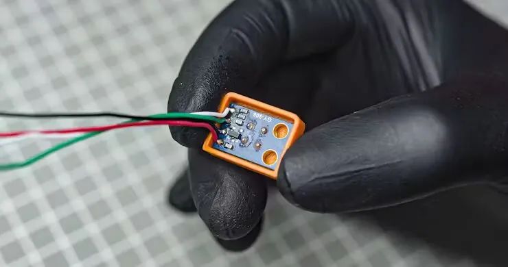
2、 将 GY-906 推入 3D 打印件中
3、 将电线穿过安装后盖上的孔
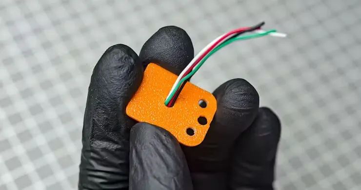
4、 卡入后盖
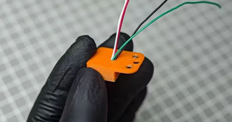
5、 用两个 M3 10mm 螺钉拧入传感器支架
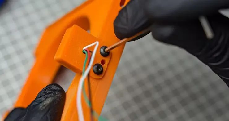
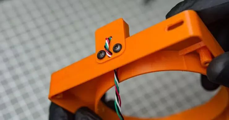
6、 将传感器线穿过中心孔进入主体。稍微捻一下电线
7、 将传感器的线与XIAO进行焊接
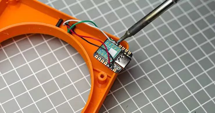
8、 为了连接OLED端子,需要焊接4根长度为14cm的导线。
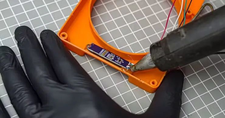
9、 将OLED显示屏与3D打印的观察窗口对齐,并将其粘合到位
10、 将OLED的电线焊接到XIAO中。
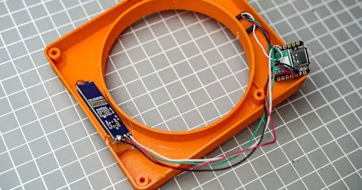
11、 将 XIAO 插入 3D 打印中,将其与 USB-C 端口的开口对齐。如有必要,用胶水将其固定到位。
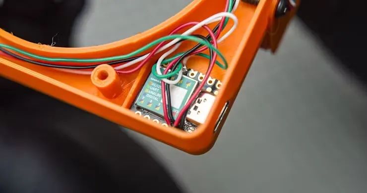
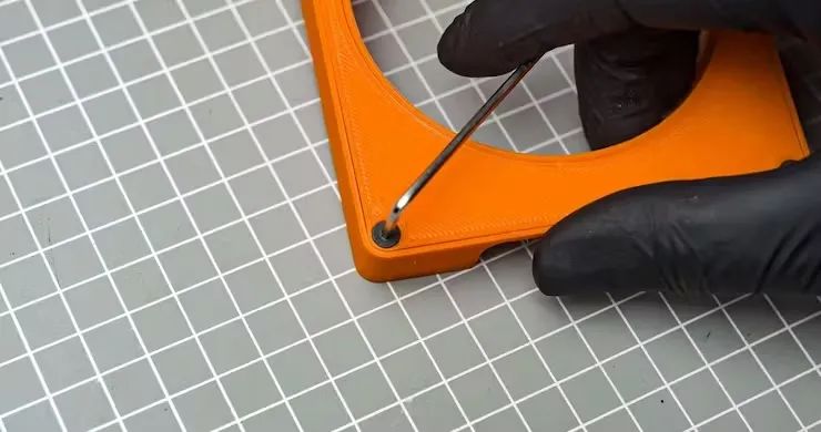
12、 用四个 M3*10mm 螺丝拧入 3D 打印背板,将打印背板拧紧。
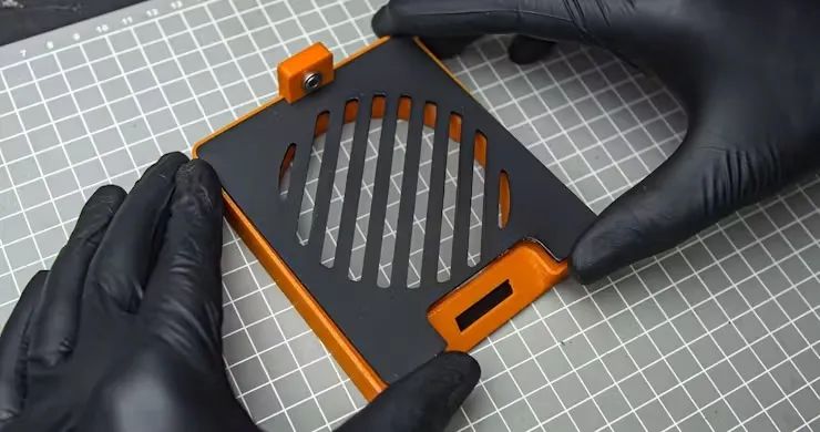
13、 盖上顶部铝板,完成完整组装。
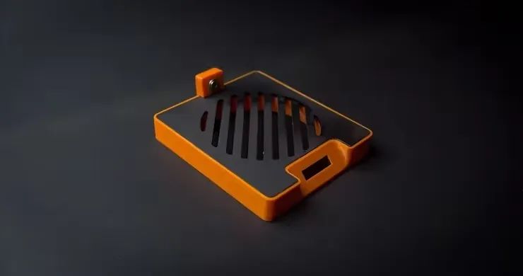
最后,本项目使用了铝材料品和3d打印件结合在一起,通过代码可以轻松的自定义温度范围,并且,此项目仅适用于导热性良好杯子。
-
智能保温杯垫2013-11-17 0
-
自制便携式智能杯垫解决您忘记喝水的烦恼2015-08-18 0
-
【AWorks280试用申请】智能杯垫2015-09-23 0
-
电池温度智能监测系统设计2018-11-05 0
-
自制智能杯垫教程2018-09-10 7372
-
了解智能杯垫应用威廉希尔官方网站 及代码设计2019-07-26 7323
-
使用ESP8266实现智能杯垫的设计资料免费下载2021-02-24 1201
-
使用SAMD21 ML评估套件进行手势识别2023-06-15 396
-
基于XIAO SAMD21开发板的数字键盘制作方案2024-09-06 495
-
基于XIAO SAMD21开发板的多功能笔筒设计方案2024-09-06 451
全部0条评论

快来发表一下你的评论吧 !
