Proteus模拟STM32F103R6微控制器之串口通信USART的方法,实验环境如下:
模拟软件:Proteus 8.11 SP0
开发环境:Keil MDK 5.33
参考资料:ST公司官方参考手册
一、原理图
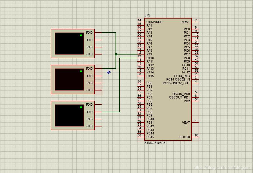
STM32F103微处理器的USART1发送:PA9,接收:PA10。
虚拟终端的发送接到STM32F103的接收,虚拟终端的接收接到STM32F103的发送。原理图如下:
 二、源码
二、源码
// NVIC配置
static void NVIC_Configuration(void)
{
NVIC_InitTypeDef NVIC_InitStructure;
// Configure the NVIC Preemption Priority Bits
NVIC_PriorityGroupConfig(NVIC_PriorityGroup_1);
// Enable the USART1 Interrupt
NVIC_InitStructure.NVIC_IRQChannel = USART1_IRQn;
NVIC_InitStructure.NVIC_IRQChannelPreemptionPriority = 1;
NVIC_InitStructure.NVIC_IRQChannelSubPriority = 1;
NVIC_InitStructure.NVIC_IRQChannelCmd = ENABLE;
NVIC_Init(&NVIC_InitStructure);
}
// USART1配置
void USART1_Config(void)
{
GPIO_InitTypeDef GPIO_InitStructure;
USART_InitTypeDef USART_InitStructure;
RCC_APB2PeriphClockCmd(RCC_APB2Periph_GPIOA, ENABLE);
RCC_APB2PeriphClockCmd(RCC_APB2Periph_USART1, ENABLE);
// Configure USART1 Tx as alternate function push-pull
GPIO_InitStructure.GPIO_Pin = GPIO_Pin_9;
GPIO_InitStructure.GPIO_Mode = GPIO_Mode_AF_PP;
GPIO_InitStructure.GPIO_Speed = GPIO_Speed_10MHz;
GPIO_Init(GPIOA, &GPIO_InitStructure);
// Configure USART1 Rx as input floating
GPIO_InitStructure.GPIO_Pin = GPIO_Pin_10;
GPIO_InitStructure.GPIO_Mode = GPIO_Mode_IN_FLOATING;
GPIO_Init(GPIOA, &GPIO_InitStructure);
// Configure USART1
USART_InitStructure.USART_BaudRate = 9600;
USART_InitStructure.USART_WordLength = USART_WordLength_8b;
USART_InitStructure.USART_StopBits = USART_StopBits_1;
USART_InitStructure.USART_Parity = USART_Parity_No;
USART_InitStructure.USART_HardwareFlowControl = USART_HardwareFlowControl_None;
USART_InitStructure.USART_Mode = USART_Mode_Rx | USART_Mode_Tx;
USART_Init(USART1, &USART_InitStructure);
// NVIC configuration
NVIC_Configuration();
// Enable USART1 Receive and Transmit interrupts
USART_ITConfig(USART1, USART_IT_RXNE, ENABLE);
USART_ITConfig(USART1, USART_IT_TXE, ENABLE);
// Enable the USART1
USART_Cmd(USART1, ENABLE);
}
// 中断处理函数
void USART1_IRQHandler(void)
{
uint16_t temp;
if(USART_GetITStatus(USART1, USART_IT_RXNE) != RESET)
{
temp = USART_ReceiveData(USART1);
USART_SendData(USART1, temp);
}
}
三、实现效果
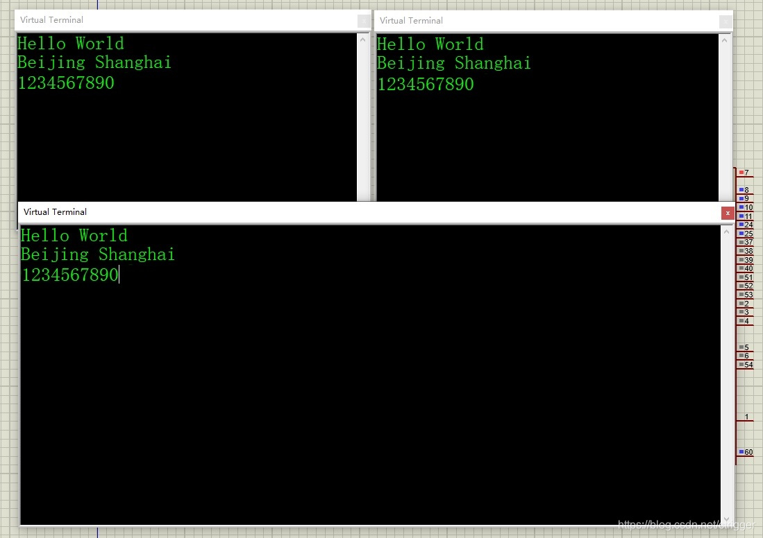
对应上面的原理图,接收是上面2个虚拟终端,发送是下面1个虚拟终端。效果图如下:

Proteus模拟STM32F103R6微控制器之串口通信USART的方法,实验环境如下:
模拟软件:Proteus 8.11 SP0
开发环境:Keil MDK 5.33
参考资料:ST公司官方参考手册
一、原理图
STM32F103微处理器的USART1发送:PA9,接收:PA10。
虚拟终端的发送接到STM32F103的接收,虚拟终端的接收接到STM32F103的发送。原理图如下:
 二、源码
二、源码
// NVIC配置
static void NVIC_Configuration(void)
{
NVIC_InitTypeDef NVIC_InitStructure;
// Configure the NVIC Preemption Priority Bits
NVIC_PriorityGroupConfig(NVIC_PriorityGroup_1);
// Enable the USART1 Interrupt
NVIC_InitStructure.NVIC_IRQChannel = USART1_IRQn;
NVIC_InitStructure.NVIC_IRQChannelPreemptionPriority = 1;
NVIC_InitStructure.NVIC_IRQChannelSubPriority = 1;
NVIC_InitStructure.NVIC_IRQChannelCmd = ENABLE;
NVIC_Init(&NVIC_InitStructure);
}
// USART1配置
void USART1_Config(void)
{
GPIO_InitTypeDef GPIO_InitStructure;
USART_InitTypeDef USART_InitStructure;
RCC_APB2PeriphClockCmd(RCC_APB2Periph_GPIOA, ENABLE);
RCC_APB2PeriphClockCmd(RCC_APB2Periph_USART1, ENABLE);
// Configure USART1 Tx as alternate function push-pull
GPIO_InitStructure.GPIO_Pin = GPIO_Pin_9;
GPIO_InitStructure.GPIO_Mode = GPIO_Mode_AF_PP;
GPIO_InitStructure.GPIO_Speed = GPIO_Speed_10MHz;
GPIO_Init(GPIOA, &GPIO_InitStructure);
// Configure USART1 Rx as input floating
GPIO_InitStructure.GPIO_Pin = GPIO_Pin_10;
GPIO_InitStructure.GPIO_Mode = GPIO_Mode_IN_FLOATING;
GPIO_Init(GPIOA, &GPIO_InitStructure);
// Configure USART1
USART_InitStructure.USART_BaudRate = 9600;
USART_InitStructure.USART_WordLength = USART_WordLength_8b;
USART_InitStructure.USART_StopBits = USART_StopBits_1;
USART_InitStructure.USART_Parity = USART_Parity_No;
USART_InitStructure.USART_HardwareFlowControl = USART_HardwareFlowControl_None;
USART_InitStructure.USART_Mode = USART_Mode_Rx | USART_Mode_Tx;
USART_Init(USART1, &USART_InitStructure);
// NVIC configuration
NVIC_Configuration();
// Enable USART1 Receive and Transmit interrupts
USART_ITConfig(USART1, USART_IT_RXNE, ENABLE);
USART_ITConfig(USART1, USART_IT_TXE, ENABLE);
// Enable the USART1
USART_Cmd(USART1, ENABLE);
}
// 中断处理函数
void USART1_IRQHandler(void)
{
uint16_t temp;
if(USART_GetITStatus(USART1, USART_IT_RXNE) != RESET)
{
temp = USART_ReceiveData(USART1);
USART_SendData(USART1, temp);
}
}
三、实现效果
对应上面的原理图,接收是上面2个虚拟终端,发送是下面1个虚拟终端。效果图如下:


 举报
举报


 举报
举报

