Arduinowilliam hill官网
登录
直播中
余华
10年用户
427经验值
擅长:可编程逻辑 嵌入式技术 处理器/DSP
私信
关注
[资料]
arduino学习笔记27 - DS1307 RTC时钟芯片与DS18B20数字温度传感器...
Arduino
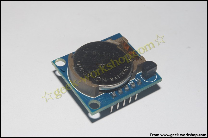
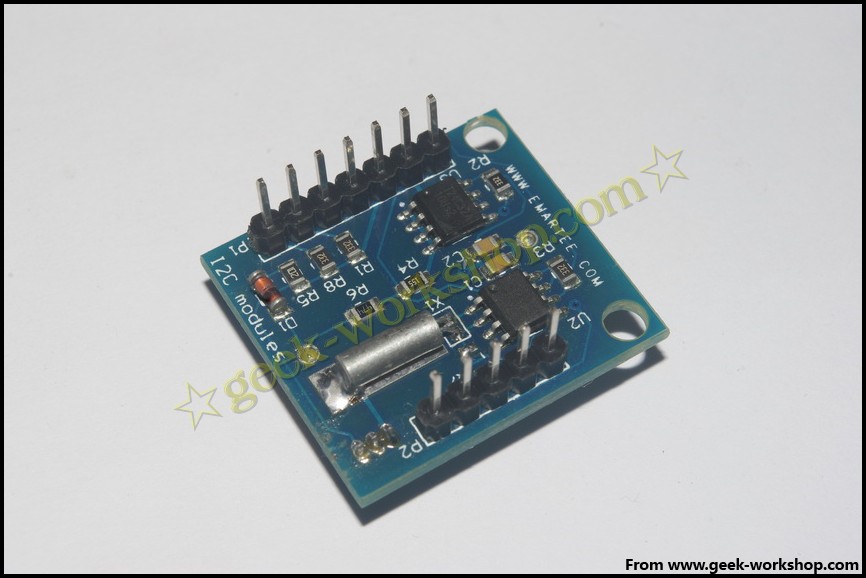
本次实验我使用的是购买的一个DS1307 RTC模块,上面集成了一个DS18B20温度传感器,还集成了另外一个存储芯片~~
先上图
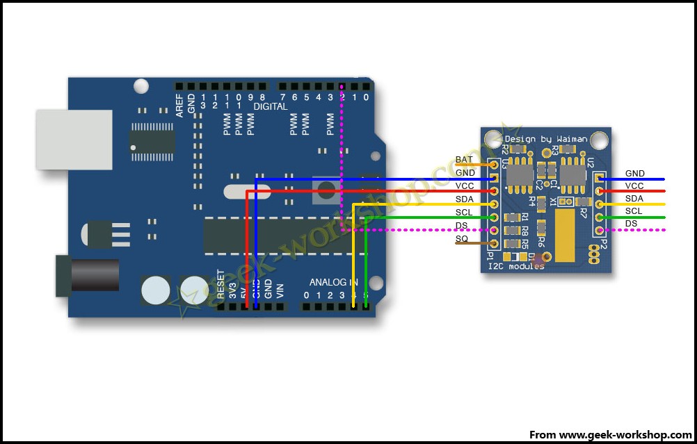
再看下硬件连接图,DS1307是I2C接口SCL接模拟5号口,SDA接模拟4号口。DS18B20是单总线模式,他的DS接口接数字2号口。
DS18B20:
DS18x20系列数字温度传感器主要有DS18S20和DS18B20(DS18S20只有9位一种工作模式,分辨率只到0.5摄氏度,DS18B20有9、10、11、12位四种工作可编程控制的模式,分辨率最高为0.0625摄氏度。),都是由美国Dallas
半导体
公司(现在改名叫Maxim)生产的。这个系列最大的特点就是采用了Maxim的专利技术1-Wire。顾名思义,1-Wire就是采用单一信号线,但可像I2C,SPI一样,同时传输时钟(clock)又传输数据(data),而且数据传输是双向的。1-Wire 使用较低的数据传输速率,通常是用来沟通小型device,如数位温度计。通过1-Wire技术可以在单一信号线的基础上构成传感器网络,Maxim起名”MicroLan”。
DS18x20的供电主要有两种模式:
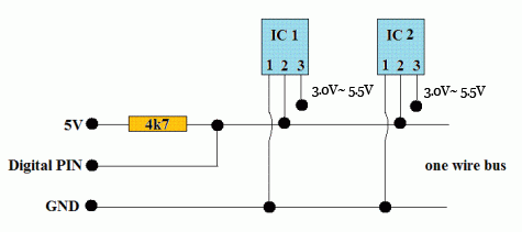
Parasite power mode/寄生供电
所谓的寄生供电是指DS18x20只需要两根接线,一根数据线,一根接地线,数据线上还要接一个4.7k上拉电阻连
电源
,数据线同时也提供了电能。DS18x20内置了电容,高电平期时把电能储存在内部电容里,低电平期内消耗内部电容里的能量工作,直到下次高电平期内再次电容充电。虽然这样的模式简化了线路同时也带来了一些缺陷:
1.
威廉希尔官方网站
的电流一般很小,只有当DS18x20进行温度转化或者写EEPROM时会高达1.5mA,当DS18x20进行上述操作时,数据线必须保持电平拉高状态直到操作结束,期间master端的Arduino不能做任何操作,DS18x20温度转化时这个时间间隔大概是750ms。
2.如果要求DS18x20有精确的转化,数据线在温度转化期间必须保证足够的能量,但当你使用多个DS18x20构成MicroLan进行多点测温时,单靠4.7k的上拉电阻无法提供足够的能量,会导致较大的测温误差。
Normal (external supply) mode/标准(外部供电)
标准外部供电模式,相比寄生供电模式,每个DS18x20需要多一条独立的电源线接独立电源。虽然多用些线,但由于外部供电,保证了每个设备的进精确度和稳定性。而且没有了上述温度转换期间Arduino不能做任何事的问题。
DS18B20的详细介绍就不多讲了,具体可以查看
william hill官网
的另一篇帖子
http://www.geek-workshop.com/for ... =198&extra=page%3D1
直接进入实战,调用DS18B20,需要使用OneWire库。
把下面代码下载进入arduino控制板。
ARDUINO 代码
复制
打印
#include
h>
// DS18S20 Temperature chip i/o
OneWire ds
(
2
)
;
// on pin 2
void
setup
(
void
)
{
// ini
ti
alize inputs/outputs
// start serial port
Serial
.
begin
(
9600
)
;
}
void
loop
(
void
)
{
byte
i;
byte
present =
0
;
byte
data
[
12
;
byte
addr
[
8
;
if
(
!ds.
search
(
addr
)
)
{
Serial
.
print
(
"No more addresses.n"
)
;
ds.
reset_search
(
)
;
return
;
}
Serial
.
print
(
"R="
)
;
for
(
i =
0
; i <
8
; i++
)
{
Serial
.
print
(
addr
[
i, HEX
)
;
Serial
.
print
(
" "
)
;
}
if
(
OneWire::
crc8
(
addr,
7
)
!= addr
[
7
)
{
Serial
.
print
(
"CRC is not valid!n"
)
;
return
;
}
if
(
addr
[
0
== 0x10
)
{
Serial
.
print
(
"Device is a DS18S20 family device.n"
)
;
}
else
if
(
addr
[
0
== 0x28
)
{
Serial
.
print
(
"Device is a DS18B20 family device.n"
)
;
}
else
{
Serial
.
print
(
"Device family is not recognized: 0x"
)
;
Serial
.
println
(
addr
[
0
,HEX
)
;
return
;
}
ds.
reset
(
)
;
ds.
select
(
addr
)
;
ds.
write
(
0x44,
1
)
;
// start conversion, with parasite power on at the end
delay
(
1000
)
;
// maybe 750ms is enough, maybe not
// we might do a ds.depower() here, but the reset will take care of it.
present = ds.
reset
(
)
;
ds.
select
(
addr
)
;
ds.
write
(
0xBE
)
;
// Read Scratchpad
Serial
.
print
(
"P="
)
;
Serial
.
print
(
present,HEX
)
;
Serial
.
print
(
" "
)
;
for
(
i =
0
; i <
9
; i++
)
{
// we need 9 bytes
data
[
i = ds.
read
(
)
;
Serial
.
print
(
data
[
i, HEX
)
;
Serial
.
print
(
" "
)
;
}
Serial
.
print
(
" CRC="
)
;
Serial
.
print
(
OneWire::
crc8
(
data,
8
)
, HEX
)
;
Serial
.
println
(
)
;
}
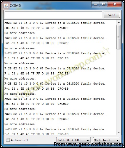
代码下载好以后打开串口编辑器,然后就会出现下面这样子的画面。
虽然我们读到了Scratchpad的数据,但是显示的是HEX16进制代码,我们还需要转化成我们能读的温度格式。这里推荐一个叫Dallas Temperature Control的Library,大大简化了这个过程。官方地址:
http://www.mile***urton.com/?titl ... ure_Control_Library
ARDUINO 代码
复制
打印
#include
h>
#include
h>
// Data wire is plugged into port 2 on the Arduino
#define ONE_WIRE_BUS
2
// Setup a oneWire instance to communicate with any OneWire devices (not just Maxim/Dallas temperature ICs)
OneWire oneWire
(
ONE_WIRE_BUS
)
;
// Pass our oneWire reference to Dallas Temperature.
DallasTemperature sensors
(
&oneWire
)
;
void
setup
(
void
)
{
// start serial port
Serial
.
begin
(
9600
)
;
Serial
.
println
(
"Dallas Temperature IC Control Library Demo"
)
;
// Start up the library
sensors.
begin
(
)
;
}
void
loop
(
void
)
{
// call sensors.requestTemperatures() to issue a global temperature
// request to all devices on the bus
Serial
.
print
(
"Requesting temperatures..."
)
;
sensors.
requestTemperatures
(
)
;
// Send the command to get temperatures
Serial
.
println
(
"DONE"
)
;
Serial
.
print
(
"Temperature for the device 1 (index 0) is: "
)
;
Serial
.
println
(
sensors.
getTem
PCB
yIndex
(
0
)
)
;
}
代码下载好以后,打开串口监视器,就可以看到当前室温了。
下面我们试用一下DS1307时钟芯片功能。
先把下面库自带测试代码下载进入arduino控制板
ARDUINO 代码
复制
打印
#include
h>
#include
h>
#include
h>
int
rtc
[
7
;
int
ledPin =
13
;
void
setup
(
)
{
DDRC|=_BV
(
2
)
|_BV
(
3
)
;
// POWER:Vcc Gnd
PORTC |=_BV
(
3
)
;
// VCC PINC3
pinMode
(
ledPin,
OUTPUT
)
;
Serial
.
begin
(
9600
)
;
RTC.
stop
(
)
;
RTC.
set
(
DS1307_SEC,
1
)
;
RTC.
set
(
DS1307_MIN,
57
)
;
RTC.
set
(
DS1307_HR,
17
)
;
RTC.
set
(
DS1307_DOW,
2
)
;
RTC.
set
(
DS1307_DATE,
18
)
;
RTC.
set
(
DS1307_MTH,
1
)
;
RTC.
set
(
DS1307_YR,
10
)
;
RTC.
start
(
)
;
}
void
loop
(
)
{
RTC.
get
(
rtc,
true
)
;
for
(
int
i=
0
; i<
7
; i++
)
{
Serial
.
print
(
rtc
[
i
)
;
Serial
.
print
(
" "
)
;
}
Serial
.
println
(
)
;
digitalWrite
(
ledPin,
HIGH
)
;
delay
(
500
)
;
digitalWrite
(
ledPin,
LOW
)
;
delay
(
500
)
;
}
然后打开串口监视器,就能看到类似下图的样子。
这个模块上还有一个T24C32A EEPROM存储器。。。下面上一个全面一点的代码,对各个期间进行测试。其中刚开始会对I2C器件进行扫描。。。代码不错,大家可以参考下。
ARDUINO 代码
复制
打印
/**
* I2CScanner.pde -- I2C bus scanner for Arduino
*
* 2009, Tod E. Kurt,
http://todbot.com/blog/
*
*/
#include
h>
#include
"Wire.h"
#include
h>
#include
h>
#include
h>
extern
"C"
{
#include
"utility/twi.h"
// from Wire library, so we can do bus scanning
}
byte
start_address =
1
;
byte
end_address =
127
;
OneWire ds
(
2
)
;
// on pin 2
byte
Tdata
[
12
;
int
sensorValue =
0
;
// value read from the pot
int
rtc
[
7
;
float
TT=
0.0
;
// Scan the I2C bus between addresses from_addr and to_addr.
// On each address, call the callback function with the address and result.
// If result==0, address was found, otherwise, address wasn't found
// (can use result to potentially get other status on the I2C bus, see twi.c)
// Assumes Wire.begin() has already been called
void
scanI2CBus
(
byte
from_addr,
byte
to_addr,
void
(
*callback
)
(
byte
address,
byte
result
)
)
{
byte
rc;
byte
data =
0
;
// not used, just an address to feed to twi_writeTo()
for
(
byte
addr = from_addr; addr <= to_addr; addr++
)
{
rc = twi_writeTo
(
addr, &data,
0
,
1
)
;
if
(
rc==
0
)
callback
(
addr, rc
)
;
}
}
// Called when address is found in scanI2CBus()
// Feel free to change this as needed
// (like adding I2C comm code to figure out what kind of I2C device is there)
void
scanFunc
(
byte
addr,
byte
result
)
{
Serial
.
print
(
"addr: "
)
;
Serial
.
print
(
addr,DEC
)
;
addr = addr<<
1
;
Serial
.
print
(
"t HEX: 0x"
)
;
Serial
.
print
(
addr,HEX
)
;
Serial
.
println
(
(
result==
0
)
?
"t found!"
:
" "
)
;
// Serial.print( (addr%4) ? "t":"n");
}
void
i2c_eeprom_write_byte
(
int
deviceaddress,
unsigned
int
eeaddress,
byte
data
)
{
int
rdata = data;
Wire
.
beginTransmission
(
deviceaddress
)
;
Wire
.
send
(
(
int
)
(
eeaddress >>
8
)
)
;
// MSB
Wire
.
send
(
(
int
)
(
eeaddress & 0xFF
)
)
;
// LSB
Wire
.
send
(
rdata
)
;
Wire
.
endTransmission
(
)
;
}
// WARNING: address is a page address, 6-bit end will wrap around
// also, data can be maximum of about 30 bytes, because the Wire library has a buffer of 32 bytes
void
i2c_eeprom_write_page
(
int
deviceaddress,
unsigned
int
eeaddresspage,
byte
* data,
byte
length
)
{
Wire
.
beginTransmission
(
deviceaddress
)
;
Wire
.
send
(
(
int
)
(
eeaddresspage >>
8
)
)
;
// MSB
Wire
.
send
(
(
int
)
(
eeaddresspage & 0xFF
)
)
;
// LSB
byte
c;
for
(
c =
0
; c < length; c++
)
Wire
.
send
(
data
[
c
)
;
Wire
.
endTransmission
(
)
;
}
byte
i2c_eeprom_read_byte
(
int
deviceaddress,
unsigned
int
eeaddress
)
{
byte
rdata = 0xFF;
Wire
.
beginTransmission
(
deviceaddress
)
;
Wire
.
send
(
(
int
)
(
eeaddress >>
8
)
)
;
// MSB
Wire
.
send
(
(
int
)
(
eeaddress & 0xFF
)
)
;
// LSB
Wire
.
endTransmission
(
)
;
Wire
.
requestFrom
(
deviceaddress,
1
)
;
if
(
Wire
.
available
(
)
)
rdata =
Wire
.
receive
(
)
;
return
rdata;
}
// maybe let's not read more than 30 or 32 bytes at a time!
void
i2c_eeprom_read_buffer
(
int
deviceaddress,
unsigned
int
eeaddress,
byte
*buffer,
int
length
)
{
Wire
.
beginTransmission
(
deviceaddress
)
;
Wire
.
send
(
(
int
)
(
eeaddress >>
8
)
)
;
// MSB
Wire
.
send
(
(
int
)
(
eeaddress & 0xFF
)
)
;
// LSB
Wire
.
endTransmission
(
)
;
Wire
.
requestFrom
(
deviceaddress,length
)
;
int
c =
0
;
for
(
c =
0
; c < length; c++
)
if
(
Wire
.
available
(
)
)
buffer
[
c =
Wire
.
receive
(
)
;
}
void
DS1302_SetOut
(
byte
data
)
{
Wire
.
beginTransmission
(
B1101000
)
;
Wire
.
send
(
7
)
;
// LSB
Wire
.
send
(
data
)
;
Wire
.
endTransmission
(
)
;
}
byte
DS1302_GetOut
(
void
)
{
byte
rdata = 0xFF;
Wire
.
beginTransmission
(
B1101000
)
;
Wire
.
send
(
7
)
;
// LSB
Wire
.
endTransmission
(
)
;
Wire
.
requestFrom
(
B1101000,
1
)
;
if
(
Wire
.
available
(
)
)
{
rdata =
Wire
.
receive
(
)
;
Serial
.
println
(
rdata,HEX
)
;
}
return
rdata;
}
void
showtime
(
void
)
{
byte
i;
Serial
.
print
(
"Time="
)
;
DS1302_SetOut
(
0x00
)
;
RTC.
get
(
rtc,
true
)
;
for
(
int
i=
0
; i<
7
; i++
)
{
Serial
.
print
(
rtc
[
i
)
;
Serial
.
print
(
" "
)
;
}
}
void
readBatVcc
(
void
)
{
sensorValue =
analogRead
(
A1
)
;
TT = sensorValue*
0.0047
;
Serial
.
print
(
"Battery: "
)
;
Serial
.
print
(
TT
)
;
Serial
.
print
(
"V"
)
;
}
// standard Arduino setup()
void
setup
(
)
{
DDRC|=_BV
(
2
)
|_BV
(
3
)
;
PORTC |=_BV
(
3
)
;
Wire
.
begin
(
)
;
Serial
.
begin
(
19200
)
;
Serial
.
println
(
"--- I2C Bus Scanner Test---"
)
;
Serial
.
print
(
"starting scanning of I2C bus from "
)
;
Serial
.
print
(
start_address,DEC
)
;
Serial
.
print
(
" to "
)
;
Serial
.
print
(
end_address,DEC
)
;
Serial
.
println
(
"..."
)
;
// start the scan, will call "scanFunc()" on result from each address
scanI2CBus
(
start_address, end_address, scanFunc
)
;
Serial
.
println
(
"n"
)
;
Serial
.
println
(
"--- EEPROM Test---"
)
;
char
somedata
[
=
"this is data from the eeprom"
;
// data to write
i2c_eeprom_write_page
(
0x50,
0
,
(
byte
*
)
somedata,
sizeof
(
somedata
)
)
;
// write to EEPROM
delay
(
100
)
;
//add a small delay
Serial
.
println
(
"Written Done"
)
;
delay
(
10
)
;
Serial
.
print
(
"Read EERPOM:"
)
;
byte
b = i2c_eeprom_read_byte
(
0x50,
0
)
;
// access the first address from the memory
int
addr=
0
;
//first address
while
(
b!=
0
)
{
Serial
.
print
(
(
char
)
b
)
;
//print content to serial port
addr++;
//increase address
b = i2c_eeprom_read_byte
(
0x50, addr
)
;
//access an address from the memory
}
Serial
.
println
(
"n"
)
;
Serial
.
println
(
""
)
;
Serial
.
println
(
"--- DS11307 RTC Test---"
)
;
showtime
(
)
;
if
(
rtc
[
6
<
2011
)
{
RTC.
stop
(
)
;
RTC.
set
(
DS1307_SEC,
1
)
;
RTC.
set
(
DS1307_MIN,
52
)
;
RTC.
set
(
DS1307_HR,
16
)
;
RTC.
set
(
DS1307_DOW,
2
)
;
RTC.
set
(
DS1307_DATE,
25
)
;
RTC.
set
(
DS1307_MTH,
1
)
;
RTC.
set
(
DS1307_YR,
11
)
;
RTC.
start
(
)
;
Serial
.
println
(
"SetTime:"
)
;
showtime
(
)
;
}
Serial
.
println
(
"nn"
)
;
Serial
.
println
(
"--- Reserve Power Test---"
)
;
Serial
.
println
(
" Close POWER!:"
)
;
PORTC &=~_BV
(
3
)
;
byte
time;
for
(
time=
0
;time<
5
;time++
)
{
digitalWrite
(
13
,
HIGH
)
;
delay
(
500
)
;
digitalWrite
(
13
,
LOW
)
;
delay
(
500
)
;
readBatVcc
(
)
;
Serial
.
println
(
""
)
;
}
PORTC |=_BV
(
3
)
;
Serial
.
println
(
"n POWER On!"
)
;
delay
(
500
)
;
showtime
(
)
;
Serial
.
println
(
"n"
)
;
Serial
.
println
(
"=== Done ==="
)
;
Serial
.
println
(
"n"
)
;
}
// standard Arduino loop()
void
loop
(
)
{
byte
i;
byte
present =
0
;
unsigned
int
Temper=
0
;
readBatVcc
(
)
;
ds.
reset
(
)
;
ds.
write
(
0xCC,
1
)
;
ds.
write
(
0x44,
1
)
;
// start conversion, with parasite power on at the end
digitalWrite
(
13
,
HIGH
)
;
delay
(
450
)
;
digitalWrite
(
13
,
LOW
)
;
delay
(
450
)
;
present = ds.
reset
(
)
;
ds.
write
(
0xCC,
1
)
;
ds.
write
(
0xBE
)
;
// Read Scratchpad
for
(
i =
0
; i <
9
; i++
)
{
// we need 9 bytes
Tdata
[
i = ds.
read
(
)
;
}
Temper =
(
Tdata
[
1
<<
8
| Tdata
[
0
)
;
TT =Temper*
0.0625
;
if
(
TT>
200
)
{
Serial
.
println
(
"t DS18B20 Not installed!"
)
;
}
else
{
Serial
.
print
(
"t Temperature="
)
;
Serial
.
println
(
TT
)
;
}
Serial
.
println
(
""
)
;
}
然后打开串口监视器,波特率要调节为19200.
附件是这次需要用到的库(适用于0022与0023 IDE):
OneWire.rar
(8.59 KB, 下载次数: 430)
DS1307.rar
(2.59 KB, 下载次数: 645)
DallasTemperature_371Beta.zip
(22.44 KB, 下载次数: 392)
补充1.0.1下可用的DS180B20库
OneWire_1.0.1.zip
(14.38 KB, 下载次数: 691)
DallasTemperature_372Beta_1.0.1.zip
(22.87 KB, 下载次数: 648)
回帖
(3)
jkhsa
2015-5-27 12:37:38
henhaohenhaohenhaohenhaohenhao
henhaohenhaohenhaohenhaohenhao
举报
陈毅
2015-7-23 22:12:18
学习了
学习了
举报
苏飘
2015-10-29 13:39:35
时钟模块是经常用到的玩意,学习了,谢谢楼主分享
时钟模块是经常用到的玩意,学习了,谢谢楼主分享
举报
更多回帖
rotate(-90deg);
回复
相关帖子
Arduino
如何调试
DS18B20
温度
传感器
2022-01-17
950
DS18B20
温度
传感器
简介
2021-12-17
2140
DS18B20
温度
传感器
实验
2021-08-18
1829
DS18B20
的
数字
温度
传感器
2021-07-29
1338
DS18B20
温度
传感器
学习
笔记
精选资料推荐
2021-07-14
893
DS18B20
温度
传感器
是什么
2020-04-27
4229
详解
DS18B20
温度
传感器
的用法
2018-09-06
9540
arduino
学习
笔记
38 -
Arduino
+
DS1307
RTC
时钟
模块与经典总结
2014-10-24
10153
arduino
学习
笔记
27
-
DS1307
RTC
时钟
芯片
与
DS18B20
数字
温度
传感器
...
2014-10-24
11326
数字
温度
传感器
DS18B20
应用
2013-03-27
1812
发帖
登录/注册
20万+
工程师都在用,
免费
PCB检查工具
无需安装、支持浏览器和手机在线查看、实时共享
查看
点击登录
登录更多精彩功能!
英国威廉希尔公司网站
william hill官网 版块
小组
免费开发板试用
ebook
直播
搜索
登录
×
20
完善资料,
赚取积分


 举报
举报
举报
举报
举报
举报


