
Simple current limiter is prog
模拟技术
2433人已加入
描述
This circuit lets you program a current limit without using microcontrollers or data converters. It consists of a charge-pump voltage doubler (U1), a current-sense amplifier (U2), and two n-channel MOSFETs. The sense-resistor value determines the maximum current limit.
A similar version of this article appeared in the May 18, 2009 issue of EE Times magazine.
Available integrated circuits can let you program a current limit, but they generally involve microcontrollers or data converters (or both). As an alternative, the Figure 1 circuit lets you program a current limit without the intervention of microcontrollers or data converters. It consists of two miniature SOT-5 devices and a few external components. The sense-resistor value determines the maximum current limit.

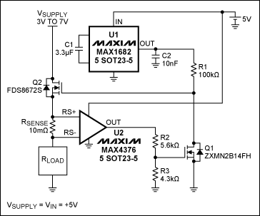
Figure 1. This circuit limits the RLOAD current to a value determined mainly by R1.
The circuit consists of a charge-pump voltage doubler (U1, MAX1682), a current-sense amplifier (U2, MAX4376), and two n-channel MOSFETs. U1 doubles the supply voltage to provide gate drive for Q2, and U2 amplifies the voltage across the sense resistor (RSENSE) with a gain of 20. This U2 output drives the Q1 gate via the R2/R3 divider, which modulates the current through R1, which in turn sets the Q1 drain voltage and Q2's gate-drive voltage.
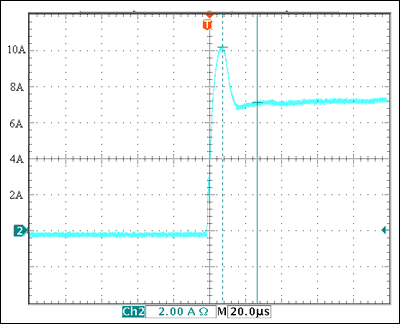
U2's output voltage is 20 times the voltage between RS+ and RS-, but has a full-scale limit of 2V. Figure 2 shows the response of this circuit when you suddenly impose a heavy (low resistance) load. It allows an initial current surge to 10A, and then (after 20µs) settles to the desired limit of 7.25A.

Figure 2. With VSUPPLY and VIN (at U1) equal to 5V, the Figure 1 circuit limits load current to 7.25V.
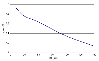
The maximum allowed in-rush current is set by the sense resistor. A 10mΩ value, for instance, allows a maximum in-rush current of 100mV/10mΩ = 10A. This steady-state limit is determined by the operating characteristics of Q1 and Q2, together with the values chosen for resistors R1–R3. Figure 3 shows the ILIMIT values obtained by varying R1 alone. To set other values of ILIMIT, you can vary the ratio R2/R3 while holding the R1 value fixed.

Figure 3. With VSUPPLY and VIN (at U1) equal to 5V, the Figure 1 circuit's steady-state current limit varies with R1 as shown.
打开APP阅读更多精彩内容
A similar version of this article appeared in the May 18, 2009 issue of EE Times magazine.
Available integrated circuits can let you program a current limit, but they generally involve microcontrollers or data converters (or both). As an alternative, the Figure 1 circuit lets you program a current limit without the intervention of microcontrollers or data converters. It consists of two miniature SOT-5 devices and a few external components. The sense-resistor value determines the maximum current limit.

Figure 1. This circuit limits the RLOAD current to a value determined mainly by R1.
The circuit consists of a charge-pump voltage doubler (U1, MAX1682), a current-sense amplifier (U2, MAX4376), and two n-channel MOSFETs. U1 doubles the supply voltage to provide gate drive for Q2, and U2 amplifies the voltage across the sense resistor (RSENSE) with a gain of 20. This U2 output drives the Q1 gate via the R2/R3 divider, which modulates the current through R1, which in turn sets the Q1 drain voltage and Q2's gate-drive voltage.
U2's output voltage is 20 times the voltage between RS+ and RS-, but has a full-scale limit of 2V. Figure 2 shows the response of this circuit when you suddenly impose a heavy (low resistance) load. It allows an initial current surge to 10A, and then (after 20µs) settles to the desired limit of 7.25A.

Figure 2. With VSUPPLY and VIN (at U1) equal to 5V, the Figure 1 circuit limits load current to 7.25V.
The maximum allowed in-rush current is set by the sense resistor. A 10mΩ value, for instance, allows a maximum in-rush current of 100mV/10mΩ = 10A. This steady-state limit is determined by the operating characteristics of Q1 and Q2, together with the values chosen for resistors R1–R3. Figure 3 shows the ILIMIT values obtained by varying R1 alone. To set other values of ILIMIT, you can vary the ratio R2/R3 while holding the R1 value fixed.

Figure 3. With VSUPPLY and VIN (at U1) equal to 5V, the Figure 1 circuit's steady-state current limit varies with R1 as shown.
声明:本文内容及配图由入驻作者撰写或者入驻合作网站授权转载。文章观点仅代表作者本人,不代表电子发烧友网立场。文章及其配图仅供工程师学习之用,如有内容侵权或者其他违规问题,请联系本站处理。
举报投诉
- 相关推荐
- current
-
请问SigmaStudio中的Limiter算法系数怎么计算2018-09-17 0
-
PROG-110可编程控制器使用入门 (全集)2009-10-23 1574
-
高侧电流传感器输出周期-High-Side Current2009-05-06 1138
-
Simple Circuit Prevents USB Cu2009-10-23 1126
-
Deluxe Charge Rate Limiter for2010-01-09 949
-
汽车热限制器的烙铁 Auto Heat Limiter fo2010-02-07 1001
-
Derive simple high-current sou2010-08-07 1346
-
PSoC 1 ISSP_Prog_Spec_TRM2017-10-10 753
-
LT6015 Demo Circuit - Precision Voltage Limiter2021-03-09 480
-
APM32 PROG开发工具使用说明2022-09-30 657
-
APM32 PROG安装包2022-11-09 411
-
KUKA系统变量:$PROG_INFO2023-05-23 1264
-
MAX17526A-MAX17526C: 5.5V to 60V, 6A Current-Limiter with OV, UV, Reverse Protection, and Power Limit Data Sheet MAX17526A-MAX17526C: 5.5V t2023-10-12 25
-
MAX17525: High-Accuracy, Adjustable Power Limiter Data Sheet MAX17525: High-Accuracy, Adjustable Power Limiter Data Sheet2023-10-13 19
全部0条评论

快来发表一下你的评论吧 !

