
先进的电力线监测需要一个高性能,同时采样模数转换器-Adva
AD技术
11人已加入
描述
Abstract: This application note explains how a simultaneous-sampling ADC like the MAX11046 can be used for advanced power-line monitoring. The article describes the fundamentals of AC power measurement by sampling. It shows a typical power-grid monitoring application and explains how international standards affect monitoring system requirements. The article summarizes the unique benefits of the MAX11046 for power-line monitoring and provides an application example.
Advanced power-line monitoring systems combine power quality, monitoring protection, and metering functions in one system. These systems allow the power utilities and customers to perform predictive maintenance, manage energy consumption and cost, control quality, and protect their equipment—all now performed more efficiently.
This type of the 3-phase power system is standard throughout the world. It is called a wye connection because of the way it appears on a phasor diagram. Each power phase's measurements are represented by a current transformer (CT) and a voltage transformer (PT). The complete system comprises four such pairs (one pair for each of the three phases plus neutral).

Figure 1. Illustration of AC power measurement by sampling.

Figure 2. Typical power-grid monitoring application. The wye design is standard throughout the world.
As Figure 2 illustrates, the MAX11044/MAX11045/MAX11046 simultaneously measure the three phases and a neutral voltage plus the currents. By performing digital processing calculations on the sampled and digitally converted data, the active, reactive, apparent energy and power factor parameters can be found. Frequency and harmonic distortion metering can be achieved by performing a Fast Fourier Transform (FFT) on the sampled data.
The measurement characteristics of the delivered energy must comply with international requirements or local standards. An example of international requirements is the European Union (EU) standard EN 50160. Table 1 summarizes the EN 50160 requirements:
Table 1. EN50160 Energy Specifications
Another EU standard, IEC62053, mandates the precision of energy metering equipment. It defines four classes of meters: Class 2, Class 1, Class 0.5, and Class 0.2. (As an example, Class 0.2 requires meter precision to be 0.2% of nominal current and voltage). For power-factor accuracy measurement, phase matching should be 0.1% or better.
For the harmonic voltage, EN 50160 mandates measurement up to the 25th order harmonic of 50Hz/60Hz voltages. However, propagation of the various "nonlinear" loads such as fluorescent lamps and switching power supplies drives measurement up to the 127th order harmonic of 50Hz/60Hz voltages.
Emerging standards like IEC61850 recommend the recording of power-system transient events with 256 samples per AC cycle or higher.
Power-monitoring equipment must measure instantaneous current and voltage values with sample rates up to 60Hz x 256 samples, or greater than 15360sps. Moreover, the power monitoring should be capable of measuring power accurately enough to accommodate the IEC62053 standard requirements.
The ADC's dynamic range for voltage measurement can be calculated from the maximum and nominal voltages to be monitored and from the required accuracy for power measurements (see Table 1 and comments on the IEC62053). For example, if a design must measure a 1.5kV (1500V) temporary overvoltage (under a fault condition) with a nominal 220V voltage measurement and a Class 0.2 (0.2%) accuracy requirement, then the total dynamic range of the voltage-measurement subsystem will need to be:
20log ((1500/220) × 2000)) = 83dB
Note: In all the calculations we assumed an intended accuracy of 0.05%, which is substantially below the standard 0.2% accuracy requirements.
Additionally, current-sensing requirements also effect ADC specifications. If the design requirements for power monitoring are the typically 100A:10A (10A nominal and 100A maximum) and Class 0.2 (0.2 %), then the total dynamic range of the current measurement subsystem will need to be:
20log ((100/10) × 2000)) = 86dB
The examples above clearly demonstrate the increasing need for higher performance in ADCs. Today 16-bit resolution at sampling rates of 16ksps, or higher, is essential. To ensure accurate 3-phase and neutral wye system current and voltage measurements, the ADC must be capable of sampling eight channels simultaneously (4 voltage and 4 current), and it must have an excellent SNR of 86dB or better.
An important feature of the MAX11046 is its effective input impedance, ZIN, which is dictated by the input capacitance and sampling frequency:
ZIN = 1/(CIN × Fsample)
Where Fsample is the sampling frequency and CIN = 15pF.
As the sampling frequency drops, input impedance increases:
266kΩ at 250ksps
2.66MΩ at 25ksps
This feature allows the MAX11046 to interface directly with measurement transformers; no external buffer is required.
Figure 3 summarizes the unique benefits of the MAX11046.

Figure 3. Description of the unique capabilities of the MAX11046 for power-measurement monitoring.
Figure 4 shows an application example generated with the MAX11046 evaluation (EV) kit board connected to power-line monitor transformers. The schematic shows the simple cost and space-efficient interface between the power-line transformers and the MAX11046.
The left oscilloscope plot shows the current and voltages from a compact fluorescent bulb, taken from the CT (current) and PT (voltage) transformers. This configuration was used as a load and test example. The software plot at the right shows the results of the CT and PT signals acquisition and reconstruction post digitization.

More detailed image (PDF, 759KB)
Figure 4.
The MAX11046 offers the most efficient 16-bit, 8-channel simultaneous sampling in an 8mm² footprint. It eliminates external buffers due to its high-impedance input structures. The device is optimized for 3-phase power-monitoring and measurement systems, and a natural choice for high-density designs that need to reduce cost and board area while increasing performance.
打开APP阅读更多精彩内容
Introduction
Power quality systems monitor in real time and record the voltages and currents from each of three phases of the multiphase power feed from power utilities. These supervisory control and data acquisition (SCADA) systems may also monitor the voltages and currents on the neutral line, thus sensing imbalanced loads or frequency harmonics. Additionally, power-metering systems measure the root mean squared (RMS) voltage and current from each of the three phases to determine power consumption.Advanced power-line monitoring systems combine power quality, monitoring protection, and metering functions in one system. These systems allow the power utilities and customers to perform predictive maintenance, manage energy consumption and cost, control quality, and protect their equipment—all now performed more efficiently.
Measurement System Architecture
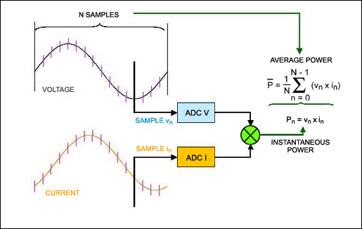
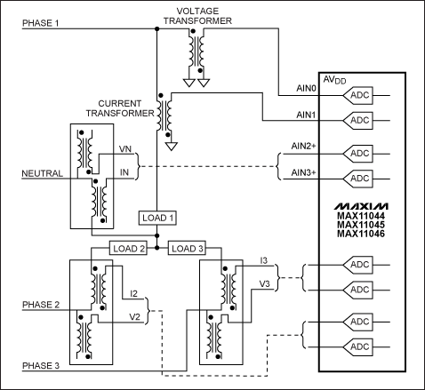
Figure 1 demonstrates the fundamentals of the AC power measurement by sampling calculations for instantaneous and average power usage. Figure 2 shows a typical power-grid monitoring application. The 3-phase power design shown in Figure 2 refers to three voltages that are offset in phase from each other by 120°, i.e., by one third of a cycle. A fourth wire called neutral is used to accommodate imbalanced loads. If loads on each of the three phases are equal, the system is balanced and no current flows though the neutral line.This type of the 3-phase power system is standard throughout the world. It is called a wye connection because of the way it appears on a phasor diagram. Each power phase's measurements are represented by a current transformer (CT) and a voltage transformer (PT). The complete system comprises four such pairs (one pair for each of the three phases plus neutral).

Figure 1. Illustration of AC power measurement by sampling.

Figure 2. Typical power-grid monitoring application. The wye design is standard throughout the world.
As Figure 2 illustrates, the MAX11044/MAX11045/MAX11046 simultaneously measure the three phases and a neutral voltage plus the currents. By performing digital processing calculations on the sampled and digitally converted data, the active, reactive, apparent energy and power factor parameters can be found. Frequency and harmonic distortion metering can be achieved by performing a Fast Fourier Transform (FFT) on the sampled data.
The measurement characteristics of the delivered energy must comply with international requirements or local standards. An example of international requirements is the European Union (EU) standard EN 50160. Table 1 summarizes the EN 50160 requirements:
Table 1. EN50160 Energy Specifications
| Supply Voltage Phenomenon | Acceptable Limits | Measurement Interval | Monitoring Period (week) | Acceptance Percentage (%) |
| Grid Frequency | 49.5Hz to 50.5Hz, 47Hz to 52Hz | 10s | 1 | 95, 100 |
| Slow Voltage Changes | 230V ±10% | 10min | 1 | 95 |
| Voltage Sags or Dips (≤ 1min) | 10 to 1000 times per year (under 85% of nominal) | 10ms | 1 year | 100 |
| Short Interruptions (≤ 3min) | 10 to 100 times per year (under 1% of nominal) | 10ms | 1 year | 100 |
| Accidental, long interruptions (> 3min) | 10 to 50 times per year (under 1% of nominal) | 10ms | 1 year | 100 |
| Temporary Overvoltages (line to ground) | Mostly < 1.5kV | 10ms | – | 100 |
| Transient Overvoltages (line to ground) | Mostly < 6kV | – | – | 100 |
| Voltage Unbalance | Mostly 2%, but occasionally 3% | 10min | 1 | 95 |
| Harmonic Voltages | 8% total harmonic distortion (THD) | 10min | 1 | 95 |
Another EU standard, IEC62053, mandates the precision of energy metering equipment. It defines four classes of meters: Class 2, Class 1, Class 0.5, and Class 0.2. (As an example, Class 0.2 requires meter precision to be 0.2% of nominal current and voltage). For power-factor accuracy measurement, phase matching should be 0.1% or better.
For the harmonic voltage, EN 50160 mandates measurement up to the 25th order harmonic of 50Hz/60Hz voltages. However, propagation of the various "nonlinear" loads such as fluorescent lamps and switching power supplies drives measurement up to the 127th order harmonic of 50Hz/60Hz voltages.
Emerging standards like IEC61850 recommend the recording of power-system transient events with 256 samples per AC cycle or higher.
Basic ADC System Requirements
Standards like EN 50160, IEC62053, and IEC61850 dictate both the minimum accuracy and sample rate needed for a modern multichannel ADC system used in power-system monitoring and metering.Power-monitoring equipment must measure instantaneous current and voltage values with sample rates up to 60Hz x 256 samples, or greater than 15360sps. Moreover, the power monitoring should be capable of measuring power accurately enough to accommodate the IEC62053 standard requirements.
The ADC's dynamic range for voltage measurement can be calculated from the maximum and nominal voltages to be monitored and from the required accuracy for power measurements (see Table 1 and comments on the IEC62053). For example, if a design must measure a 1.5kV (1500V) temporary overvoltage (under a fault condition) with a nominal 220V voltage measurement and a Class 0.2 (0.2%) accuracy requirement, then the total dynamic range of the voltage-measurement subsystem will need to be:
20log ((1500/220) × 2000)) = 83dB
Note: In all the calculations we assumed an intended accuracy of 0.05%, which is substantially below the standard 0.2% accuracy requirements.
Additionally, current-sensing requirements also effect ADC specifications. If the design requirements for power monitoring are the typically 100A:10A (10A nominal and 100A maximum) and Class 0.2 (0.2 %), then the total dynamic range of the current measurement subsystem will need to be:
20log ((100/10) × 2000)) = 86dB
The examples above clearly demonstrate the increasing need for higher performance in ADCs. Today 16-bit resolution at sampling rates of 16ksps, or higher, is essential. To ensure accurate 3-phase and neutral wye system current and voltage measurements, the ADC must be capable of sampling eight channels simultaneously (4 voltage and 4 current), and it must have an excellent SNR of 86dB or better.
Power-Line Monitoring Capabilities of the MAX11046 ADC
The MAX11046 includes eight simultaneous-sampling, low-power, 16-bit, 250ksps, successive-approximation ADCs in a single package. It is ideally suited to power-system monitoring and measurement applications:An important feature of the MAX11046 is its effective input impedance, ZIN, which is dictated by the input capacitance and sampling frequency:
ZIN = 1/(CIN × Fsample)
Where Fsample is the sampling frequency and CIN = 15pF.
As the sampling frequency drops, input impedance increases:
266kΩ at 250ksps
2.66MΩ at 25ksps
This feature allows the MAX11046 to interface directly with measurement transformers; no external buffer is required.
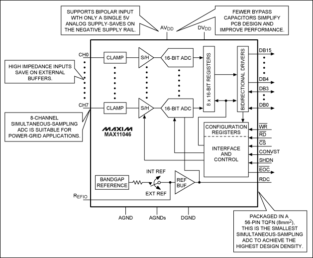
Figure 3 summarizes the unique benefits of the MAX11046.

Figure 3. Description of the unique capabilities of the MAX11046 for power-measurement monitoring.
Figure 4 shows an application example generated with the MAX11046 evaluation (EV) kit board connected to power-line monitor transformers. The schematic shows the simple cost and space-efficient interface between the power-line transformers and the MAX11046.
The left oscilloscope plot shows the current and voltages from a compact fluorescent bulb, taken from the CT (current) and PT (voltage) transformers. This configuration was used as a load and test example. The software plot at the right shows the results of the CT and PT signals acquisition and reconstruction post digitization.

More detailed image (PDF, 759KB)
Figure 4.
Conclusion
Rising worldwide power demands are driving increased investment in the power-delivery infrastructure. A critical element of these new power delivery systems are multichannel supervisory control and data acquisition (SCADA) systems, which include digital relays for automated power-delivery monitoring, and fault-detection and protection. SCADA systems require multichannel high-resolution ADCs such as MAX11046.The MAX11046 offers the most efficient 16-bit, 8-channel simultaneous sampling in an 8mm² footprint. It eliminates external buffers due to its high-impedance input structures. The device is optimized for 3-phase power-monitoring and measurement systems, and a natural choice for high-density designs that need to reduce cost and board area while increasing performance.
声明:本文内容及配图由入驻作者撰写或者入驻合作网站授权转载。文章观点仅代表作者本人,不代表电子发烧友网立场。文章及其配图仅供工程师学习之用,如有内容侵权或者其他违规问题,请联系本站处理。
举报投诉
- 相关推荐
- 转换器
-
多通道采样的精准的电力线监测2016-02-24 0
-
AD9446BSVZ-100模数转换器2018-10-31 0
-
AD9051BRSZRL模数转换器2018-11-06 0
-
SAR模数转换器AD7989-1和AD7989-52018-11-29 0
-
带有I2C接口的16位高性能DS模数转换器2020-05-01 0
-
电力线通信模拟前端收发器MAX2980相关资料分享2021-05-17 0
-
为什么我们需要模数转换器?哪个ADC转换器更好?2023-02-15 0
-
MAX2980,中文资料,pdf datasheet(电力线2009-07-23 503
-
利用高性能同时采样ADC降低高级电力线监测系统的成本2009-10-31 698
-
先进的电力线监测需要高性能同时采样ADC2010-04-10 656
-
MAX2980电力线通信模拟前端收发器2011-03-30 697
-
如何降低模数转换器的性能2018-12-12 4135
-
高性能全集成逐次逼近寄存器型模数转换器2022-10-31 390
-
利用高性能、同步采样ADC,降低高级电力线监控的系统成本2023-02-27 1395
-
高级电力线监控需要高性能、同步采样ADC2023-02-27 1018
全部0条评论

快来发表一下你的评论吧 !

