
如何通过流策略实现VLAN间的访问权限?
电子说
描述
前言
VLAN(Virtual Local Area Network)即虚拟局域网,是将一个物理的LAN在逻辑上划分成多个广播域的通信技术。
本文主要介绍通过流策略实现VLAN间三层隔离,也就是我们常说的对用户增加访问权限。
01
过流策略实现VLAN间三层隔离
1.1 组网需求
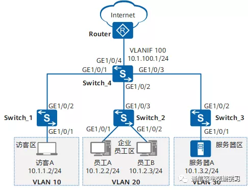
如图 1 所示,为了通信的安全性,某公司将访客、员工、服务器分别划分到VLAN10、VLAN20、VLAN30中。公司希望:
员工、服务器主机、访客均能访问Internet。
访客只能访问Internet,不能与其他任何VLAN的用户通信。
员工A可以访问服务器区的所有资源,但其他员工只能访问服务器A的21端口(FTP服务)。

图片
图 1 配置通过流策略实现VLAN间三层隔离组网图
1.2 配置思路
可采用如下思路配置通过流策略实现VLAN间互访控制:
配置VLAN并将各接口加入VLAN,使员工、服务器、访客间二层隔离。
配置VLANIF接口及其IP地址,使员工、服务器、访客间可三层互通。
配置上行路由,使员工、服务器、访客均可通过Switch访问Internet。
配置并应用流策略,使员工A可以访问服务器区的所有资源,其他员工只能访问服务器A的21端口,且只允许员工访问服务器;使访客只能访问Internet。
1.3 操作步骤
【1】配置VLAN并将各接口加入VLAN,使员工、服务器、访客间二层隔离
# 在Switch_1上创建VLAN10,并将接口GE1/0/1以Untagged方式加入VLAN10,接口GE1/0/2以Tagged方式加入VLAN10。Switch_2和Switch_3的配置与Switch_1类似,不再赘述。
[HUAWEI] sysname Switch_1
[Switch_1] vlan batch 10
[Switch_1] interface gigabitethernet 1/0/1
[Switch_1-GigabitEthernet1/0/1] port link-type access
[Switch_1-GigabitEthernet1/0/1] port default vlan 10
[Switch_1-GigabitEthernet1/0/1] quit
[Switch_1] interface gigabitethernet 1/0/2
[Switch_1-GigabitEthernet1/0/2] port link-type trunk
[Switch_1-GigabitEthernet1/0/2] port trunk allow-pass vlan 10
[Switch_1-GigabitEthernet1/0/2] quit
# 在Switch_4上创建VLAN10、VLAN20、VLAN30、VLAN100,并配置接口GE1/0/1~GE1/0/4分别以Tagged方式加入VLAN10、VLAN20、VLAN30、VLAN100。
[HUAWEI] sysname Switch_4
[Switch_4] vlan batch 10 20 30 100
[Switch_4] interface gigabitethernet 1/0/1
[Switch_4-GigabitEthernet1/0/1] port link-type trunk
[Switch_4-GigabitEthernet1/0/1] port trunk allow-pass vlan 10
[Switch_4-GigabitEthernet1/0/1] quit
[Switch_4] interface gigabitethernet 1/0/2
[Switch_4-GigabitEthernet1/0/2] port link-type trunk
[Switch_4-GigabitEthernet1/0/2] port trunk allow-pass vlan 20
[Switch_4-GigabitEthernet1/0/2] quit
[Switch_4] interface gigabitethernet 1/0/3
[Switch_4-GigabitEthernet1/0/3] port link-type trunk
[Switch_4-GigabitEthernet1/0/3] port trunk allow-pass vlan 30
[Switch_4-GigabitEthernet1/0/3] quit
[Switch_4] interface gigabitethernet 1/0/4
[Switch_4-GigabitEthernet1/0/4] port link-type trunk
[Switch_4-GigabitEthernet1/0/4] port trunk allow-pass vlan 100
[Switch_4-GigabitEthernet1/0/4] quit

【2】配置VLANIF接口及其IP地址,使员工、服务器、访客间可以三层互通
# 在Switch_4上创建VLANIF10、VLANIF20、VLANIF30、VLANIF100,并分别配置其IP地址为10.1.1.1/24、10.1.2.1/24、10.1.3.1/24、10.1.100.1/24。
[Switch_4] interface vlanif 10
[Switch_4-Vlanif10] ip address 10.1.1.1 24
[Switch_4-Vlanif10] quit
[Switch_4] interface vlanif 20
[Switch_4-Vlanif20] ip address 10.1.2.1 24
[Switch_4-Vlanif20] quit
[Switch_4] interface vlanif 30
[Switch_4-Vlanif30] ip address 10.1.3.1 24
[Switch_4-Vlanif30] quit
[Switch_4] interface vlanif 100
[Switch_4-Vlanif100] ip address 10.1.100.1 24
[Switch_4-Vlanif100] quit
【3】配置上行路由,使员工、服务器、访客均可通过Switch访问Internet。
# 在Switch_4上配置OSPF基本功能,发布用户网段以及Switch_4与Router之间的互联网段。
[Switch_4] ospf
[Switch_4-ospf-1] area 0
[Switch_4-ospf-1-area-0.0.0.0] network 10.1.1.0 0.0.0.255
[Switch_4-ospf-1-area-0.0.0.0] network 10.1.2.0 0.0.0.255
[Switch_4-ospf-1-area-0.0.0.0] network 10.1.3.0 0.0.0.255
[Switch_4-ospf-1-area-0.0.0.0] network 10.1.100.0 0.0.0.255
[Switch_4-ospf-1-area-0.0.0.0] quit
[Switch_4-ospf-1] quit
Router上需要进行如下配置:
将连接Switch的接口以Tagged方式加入VLAN100,并指定VLANIF100的IP地址与10.1.100.1在同一网段。
配置OSPF基本功能,并发布Switch与Router之间的互联网段。
【4】配置并应用流策略,控制员工、访客、服务器之间的访问
A、通过ACL定义每个流
# 在Switch_4上配置ACL 3000,禁止访客访问员工区和服务器区。
[Switch_4] acl 3000
[Switch_4-acl-adv-3000] rule deny ip destination 10.1.2.1 0.0.0.255
[Switch_4-acl-adv-3000] rule deny ip destination 10.1.3.1 0.0.0.255
[Switch_4-acl-adv-3000] quit
# 在Switch_4上配置ACL 3001,使员工A可以访问服务器区的所有资源,其他员工只能访问服务器A的21端口。
[Switch_4] acl 3001
[Switch_4-acl-adv-3001] rule permit ip source 10.1.2.2 0 destination 10.1.3.1 0.0.0.255
[Switch_4-acl-adv-3001] rule permit tcp destination 10.1.3.2 0 destination-port eq 21
[Switch_4-acl-adv-3001] rule deny ip destination 10.1.3.1 0.0.0.255
[Switch_4-acl-adv-3001] quit
B、配置流分类,区分不同的流
# 在Switch_4上创建流分类c_custom、c_staff,并分别配置匹配规则3000、3001。
[Switch_4] traffic classifier c_custom
[Switch_4-classifier-c_custom] if-match acl 3000
[Switch_4-classifier-c_custom] quit
[Switch_4] traffic classifier c_staff
[Switch_4-classifier-c_staff] if-match acl 3001
[Switch_4-classifier-c_staff] quit
C、配置流行为,指定流动作
# 在Switch_4上创建流行为b1,并配置允许动作。
[Switch_4] traffic behavior b1
[Switch_4-behavior-b1] permit
[Switch_4-behavior-b1] quit
D、配置流策略,关联流分类和流行为
# 在Switch_4上创建流策略p_custom、p_staff,并分别将流分类c_custom、c_staff与流行为b1关联。
[Switch_4] traffic policy p_custom
[Switch_4-trafficpolicy-p_custom] classifier c_custom behavior b1
[Switch_4-trafficpolicy-p_custom] quit
[Switch_4] traffic policy p_staff
[Switch_4-trafficpolicy-p_staff] classifier c_staff behavior b1
[Switch_4-trafficpolicy-p_staff] quit
E、应用流策略,实现员工、访客、服务器之间的访问控制
# 在Switch_4上,分别在VLAN10、VLAN20的入方向应用流策略p_custom、p_staff。
[Switch_4] vlan 10
[Switch_4-vlan10] traffic-policy p_custom inbo
审核编辑:刘清
-
华为路由器交换机VLAN配置实例2009-05-25 0
-
请问如何实现VLAN?2019-11-07 0
-
Linux改变文件或目录的访问权限命令2009-01-18 1201
-
基于RBAC的B/S系统访问控制设计2011-06-07 841
-
VLAN的实现及VLAN间路由2012-02-28 912
-
18-VLAN访问列表配置命令2016-12-17 675
-
不同vlan间的通信简单配置的三种方式解析2017-12-05 58769
-
一文详解交换机间VLAN的通信过程2020-11-23 7457
-
通过二层技术,如何实现不同VLAN间通讯2023-03-07 9758
-
使用路由器子接口单臂路由实现VLAN间互相访问2023-06-02 2323
-
VLAN间路由2023-06-25 230
-
VLAN的基础知识总结2023-09-04 799
-
linux文件访问权限怎么设置2023-11-23 1516
-
如何通过单臂路由实现VLAN间通信?2023-12-07 1279
-
VoIP?Voice VLAN?是如何实现的?2023-12-25 900
全部0条评论

快来发表一下你的评论吧 !

