

如何使用射频模块进行PIC到PIC的无线通信
通信网络
描述
大家好,今天在这个项目中,我们将射频接收器和发射器模块与PIC微控制器连接,并在两个不同的PIC微控制器之间进行无线通信。
在这个项目中,我们将做以下事情:-
我们将使用 PIC16F877A 作为发射器,使用PIC18F4520作为接收器部分。
我们将键盘和LCD与PIC微控制器连接。
在发射器方面,我们将键盘与PIC接口并传输数据。在接收器侧,我们将无线接收数据并显示按下LCD上的哪个键。
我们将使用编码器和解码器IC来传输4位数据。
接收频率将为433Mhz,使用市场上廉价的RF TX-RX模块。
433MHz射频发射器和接收器模块:
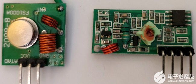
这些是我们在项目中使用的发射器和接收器模块。它是433 MHz最便宜的模块,这些模块在一个通道中接受串行数据。
如果我们看到模块的规格,变送器的额定工作电压为3.5-12V,发射距离为20-200米。它确实以433 MHz 频率的 AM(音频调制)协议传输。我们可以以 4KB/S 的速度以 10mW 的功率传输数据。
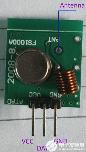
在上图中,我们可以看到发射器模块的引脚。从左到右,引脚是VCC,DATA和GND。我们还可以添加天线并将其焊接在上图中表示的点上。
对于接收器规格,接收器的额定电压为5V 直流,静态电流为 4MA作为输入。接收频率为433.92 MHz,灵敏度为-105DB。
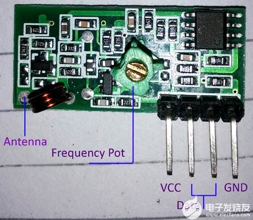
在上图中,我们可以看到接收器模块的引脚。四个引脚从左到右依次为VCC、数据、数据和GND。中间的两个引脚在内部连接。我们可以使用任何一个或两个。但是,最好同时使用两者来降低噪声耦合。
此外,数据表中没有提到一件事,模块中间的可变电感或POT用于频率校准。如果我们无法接收传输的数据,则发射和接收频率可能不匹配。这是一个射频威廉希尔官方网站 ,我们需要将发射器调谐到完美的发射频率点。此外,与发射器相同,该模块也有一个天线端口;我们可以以线圈形式焊接焊丝,以获得更长的接收时间。
传输范围取决于提供给发射器的电压和两侧天线的长度。对于这个特定的项目,我们没有使用外部天线,而是在发射器侧使用了5V。我们检查了5米的距离,效果很好。
编码器和解码器的需求:
这种射频传感器几乎没有缺点:-
单向沟通。
只有一个通道
非常噪音干扰。
由于这个缺点,我们使用了编码器和解码器IC,HT12D和HT12E。D代表解码器,将在接收器侧使用,E代表编码器,将在发射器侧使用。该 IC 提供4 个通道。此外,由于编码和解码,噪声水平非常低。
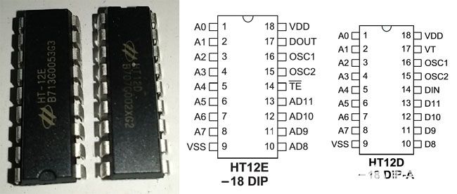
在上图中,左边是解码器HT12D,右边是编码器HT12E。两个IC是相同的。A0 到 A7用于特殊编码。我们可以使用微控制器引脚来控制这些引脚并设置配置。另一侧需要匹配相同的配置。如果两种配置准确且匹配,我们可以接收数据。这 8 个引脚可以连接到Gnd或VCC或保持打开状态。无论我们在编码器中进行什么配置,我们都需要匹配解码器上的连接。在本项目中,我们将为编码器和解码器保留这 8 个引脚。9 和 18 引脚分别为 VSS 和 VDD。我们可以使用HT12D中的VT引脚作为通知目的。对于这个项目,我们没有使用它。TE引脚用于传输使能或禁用引脚。
重要的部分是我们需要连接电阻的OSC引脚,以便为编码器和解码器提供振荡。解码器需要比解码器更高的振荡。通常,编码器电阻值为1Meg,解码器值为33k。我们将在项目中使用这些电阻器。
DOUT引脚是 HT12E 上的射频发射器数据引脚,HT12D中的DIN引脚用于连接射频模块数据引脚。
在HT12E中,AD8至AD11是四通道输入,通过RF模块进行转换和串行传输,而在HT12D中发生的情况恰恰相反,串行数据被接收和解码,我们在4个引脚D8至D11上获得4位并行输出。
所需组件:
2 - 面包板
1 - 液晶显示器 16x2
1 – 键盘
HT12D 和 HT12E 对
射频模块
1- 10K预设
2 – 4.7k 电阻器
1- 1M 电阻器
1- 33k 电阻器
2- 33pF 陶瓷电容器
1 – 20兆赫晶体
伯格斯
很少的单股线。
PIC16F877A 单片机
PIC18F4520 单片机
一把螺丝刀用于控制频率的锅,需要与人体绝缘。
威廉希尔官方网站 图:
变送器侧威廉希尔官方网站 图 (PIC16F877A):
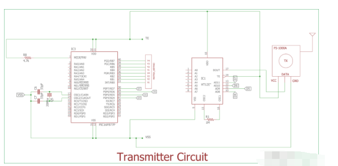
我们使用PIC16F877A进行传输。六角键盘通过PORTB连接,4 个通道连接在PORTD的最后4位。
引脚如下-
1.AD11 = RD7
2.AD10 = RD6
3.AD9 = RD5
4.AD8 = RD4
接收器侧威廉希尔官方网站 图 (PIC18F4520):
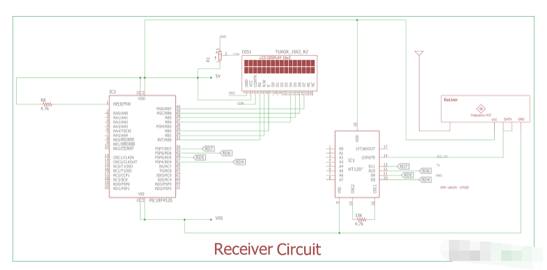
在上图中,显示了接收器威廉希尔官方网站 。液晶屏通过端口连接。我们在这个项目中使用了PIC18F4520的内部振荡器。4 个通道的连接方式与我们之前在发射器威廉希尔官方网站 中的连接方式相同。
这是发射器侧-
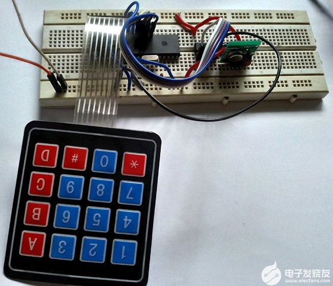
接收器侧位于单独的试验板中-
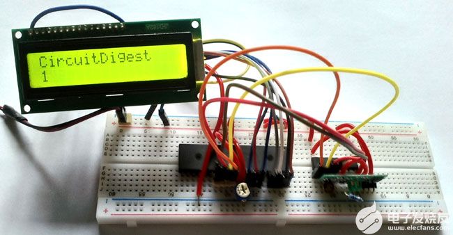
代码说明:
代码分为两部分,一部分用于发射器,另一部分用于接收器。
射频发射器的PIC16F877A代码:
与往常一样,首先,我们需要在图片微控制器中设置配置位,定义一些宏,包括库和晶体频率。编码器 ic 的AD8-AD11端口定义为端口RF_TX。您可以在最后给出的完整代码中检查所有这些代码的代码。
我们使用了两个函数,void system_init(void)和void encode_rf_sender(char data)。
system_init用于引脚初始化和键盘初始化。键盘初始化从键盘库调用。
键盘端口也在键盘 .h中定义。我们使用TRISD=0x00将PORTD作为输出,并将RF_TX端口设置为默认状态0x00。
void system_init(void){
TRISD = 0x00;
RF_TX = 0x00;
keyboard_initialization();
}
在
encode_rf_sender
中,我们根据按下的按钮更改了 4 针状态。我们创建了
16
个不同的
十六进制值
或
PORTD
状态,具体取决于按下的
(4x4) 16
个不同的按钮。
void encode_rf_sender (char data){
if(data=='1')
RF_TX=0x10;
if(data=='2')
RF_TX=0x20;
if(data=='3')
……… …. ..
…. ….
在main函数中,我们首先使用switch_press_scan()函数接收键盘按钮按下的数据,并将数据存储在键变量中。之后,我们使用encode_rf_sender()函数对数据进行编码并更改PORTD状态。
射频接收器的PIC18F4520代码:
与往常一样,我们首先在PIC18f4520中设置配置位。它与PIC16F877A略有不同,您可以在随附的zip文件中检查代码。
我们包含了LCD头文件。使用PORTD线路定义了解码器IC跨PORTD的D8-D11端口连接#define RF_RX连接与编码器部分中使用的连接相同。LCD端口声明也在lcd.c文件中完成。
#include
#include "supporing_cfilelcd.h"
#define RF_RX PORTD
如前所述,我们为18F4520使用内部振荡器,我们使用了system_init函数,其中我们配置 18F4520 的OSCON寄存器以将内部振荡器设置为8 MHz。我们还为LCD引脚和解码器引脚设置了TRIS位。由于HT-12D在D8-D11端口提供输出,我们需要将PORTD配置为输入以接收输出。
void system_init (void){
OSCCON = 0b01111110; // 8Mhz, , intosc
//OSCTUNE = 0b01001111; // PLL enable, Max prescaler 8x4 = 32Mhz
TRISB = 0x00;
TRISD = 0xFF; // Last 4 bit as input bit.
}
我们将OSCON寄存器配置为8MHz,还将端口 B作为输出,端口D作为输入。
下面的功能是使用上一个变送器部分中使用的完全相反的逻辑制作的。在这里,我们从端口 D获得相同的十六进制值,并通过该十六进制值确定在发射器部分中按下了哪个开关。我们可以识别每个按键并将相应的字符提交给LCD。
void rf_analysis (unsigned char recived_byte){
if(recived_byte==0x10)
lcd_data('1');
if(recived_byte==0x20)
lcd_data('2');
if(recived_byte==0x30)
……. ….. …
… ………..
从lcd.c文件调用lcd_data。
在主函数中,我们首先初始化系统和LCD。我们获取一个可变字节,并存储从端口 D接收的十六进制值。然后通过该功能rf_analysis我们可以在LCD上打印字符。
void main(void) {
unsigned char byte = 0;
system_init();
lcd_init();
while(1){
lcd_com(0x80);
lcd_puts("CircuitDigest");
lcd_com (0xC0);
byte = RF_RX;
rf_analysis(byte);
lcd_com (0xC0);
}
return;
}
在运行它之前,我们已经调整了威廉希尔官方网站 。首先,我们按下键盘中的“D”按钮。因此,0xF0由RF发射器连续传输。然后,我们调整接收器威廉希尔官方网站 ,直到LCD显示字符“D”。有时模块从制造商处正确调谐,有时则没有。如果一切都正确连接并且没有在LCD中得到按钮按下的值,则RF接收器可能未调谐。我们使用绝缘螺丝刀来减少由于我们的身体电感而导致的错误调谐可能性。
这就是如何将射频模块连接到 PIC微控制器,并使用射频传感器在两个 PIC 微控制器之间进行无线通信的方式。
PIC code for Transmitter Side:
/*
* File: main.c
* Author: Sourav Gupta
* By:- circuitdigest.com
* Created on April 13, 2018, 2:26 PM
*/
// PIC16F877A Configuration Bit Settings
// 'C' source line config statements
// CONFIG
#pragma config FOSC = HS // Oscillator Selection bits (HS oscillator)
#pragma config WDTE = OFF // Watchdog Timer Enable bit (WDT disabled)
#pragma config PWRTE = OFF // Power-up Timer Enable bit (PWRT disabled)
#pragma config BOREN = ON // Brown-out Reset Enable bit (BOR enabled)
#pragma config LVP = OFF // Low-Voltage (Single-Supply) In-Circuit Serial Programming Enable bit (RB3/PGM pin has PGM function; low-voltage programming enabled)
#pragma config CPD = OFF // Data EEPROM Memory Code Protection bit (Data EEPROM code protection off)
#pragma config WRT = OFF // Flash Program Memory Write Enable bits (Write protection off; all program memory may be written to by EECON control)
#pragma config CP = OFF // Flash Program Memory Code Protection bit (Code protection off)
#include
#include
#include
#include "supporing_cfile/Keypad.h"
#define RF_TX PORTD
/*
Hardware related definition
*/
#define _XTAL_FREQ 200000000 //Crystal Frequency, used in delay
/*
Other Specific definition
*/
void system_init(void);
void encode_rf_sender (char data);
void main(void){
system_init();
char Key = 'n';
while(1){
Key = switch_press_scan();
encode_rf_sender(Key);
}
}
/*
* System Init
*/
void system_init(void){
TRISD = 0x00;
RF_TX = 0x00;
keyboard_initialization();
}
void encode_rf_sender (char data){
if(data=='1')
RF_TX=0x10;
if(data=='2')
RF_TX=0x20;
if(data=='3')
RF_TX=0x30;
if(data=='4')
RF_TX=0x40;
if(data=='5')
RF_TX=0x50;
if(data=='6')
RF_TX=0x60;
if(data=='7')
RF_TX=0x70;
if(data=='8')
RF_TX=0x80;
if(data=='9')
RF_TX=0x90;
if(data=='0')
RF_TX=0x00;
if(data=='*')
RF_TX=0xa0;
if(data=='#')
RF_TX=0xb0;
if(data=='A')
RF_TX=0xc0;
if(data=='B')
RF_TX=0xd0;
if(data=='C')
RF_TX=0xe0;
if(data=='D')
RF_TX=0xf0;
}
PIC code for Receiver Side:
/*
* File: main.c
* Author: Sourav Gupta
*CircuitDigest.com
* Created on 17 May 2018, 12:18
*/
// PIC18F4520 Configuration Bit Settings
// 'C' source line config statements
// CONFIG1H
#pragma config OSC = INTIO7 // Oscillator Selection bits (Internal oscillator block, CLKO function on RA6, port function on RA7)
#pragma config FCMEN = OFF // Fail-Safe Clock Monitor Enable bit (Fail-Safe Clock Monitor disabled)
#pragma config IESO = OFF // Internal/External Oscillator Switchover bit (Oscillator Switchover mode disabled)
// CONFIG2L
#pragma config PWRT = OFF // Power-up Timer Enable bit (PWRT disabled)
#pragma config BOREN = SBORDIS // Brown-out Reset Enable bits (Brown-out Reset enabled in hardware only (SBOREN is disabled))
#pragma config BORV = 3 // Brown Out Reset Voltage bits (Minimum setting)
// CONFIG2H
#pragma config WDT = ON // Watchdog Timer Enable bit (WDT enabled)
#pragma config WDTPS = 32768 // Watchdog Timer Postscale Select bits (1:32768)
// CONFIG3H
#pragma config CCP2MX = PORTC // CCP2 MUX bit (CCP2 input/output is multiplexed with RC1)
#pragma config PBADEN = OFF // PORTB A/D Enable bit (PORTB<4:0> pins are configured as analog input channels on Reset)
#pragma config LPT1OSC = OFF // Low-Power Timer1 Oscillator Enable bit (Timer1 configured for higher power operation)
#pragma config MCLRE = ON // MCLR Pin Enable bit (MCLR pin enabled; RE3 input pin disabled)
// CONFIG4L
#pragma config STVREN = ON // Stack Full/Underflow Reset Enable bit (Stack full/underflow will cause Reset)
#pragma config LVP = OFF // Single-Supply ICSP Enable bit (Single-Supply ICSP disabled)
#pragma config XINST = OFF // Extended Instruction Set Enable bit (Instruction set extension and Indexed Addressing mode disabled (Legacy mode))
// CONFIG5L
#pragma config CP0 = OFF // Code Protection bit (Block 0 (000800-001FFFh) not code-protected)
#pragma config CP1 = OFF // Code Protection bit (Block 1 (002000-003FFFh) not code-protected)
#pragma config CP2 = OFF // Code Protection bit (Block 2 (004000-005FFFh) not code-protected)
#pragma config CP3 = OFF // Code Protection bit (Block 3 (006000-007FFFh) not code-protected)
// CONFIG5H
#pragma config CPB = OFF // Boot Block Code Protection bit (Boot block (000000-0007FFh) not code-protected)
#pragma config CPD = OFF // Data EEPROM Code Protection bit (Data EEPROM not code-protected)
// CONFIG6L
#pragma config WRT0 = OFF // Write Protection bit (Block 0 (000800-001FFFh) not write-protected)
#pragma config WRT1 = OFF // Write Protection bit (Block 1 (002000-003FFFh) not write-protected)
#pragma config WRT2 = OFF // Write Protection bit (Block 2 (004000-005FFFh) not write-protected)
#pragma config WRT3 = OFF // Write Protection bit (Block 3 (006000-007FFFh) not write-protected)
// CONFIG6H
#pragma config WRTC = OFF // Configuration Register Write Protection bit (Configuration registers (300000-3000FFh) not write-protected)
#pragma config WRTB = OFF // Boot Block Write Protection bit (Boot block (000000-0007FFh) not write-protected)
#pragma config WRTD = OFF // Data EEPROM Write Protection bit (Data EEPROM not write-protected)
// CONFIG7L
#pragma config EBTR0 = OFF // Table Read Protection bit (Block 0 (000800-001FFFh) not protected from table reads executed in other blocks)
#pragma config EBTR1 = OFF // Table Read Protection bit (Block 1 (002000-003FFFh) not protected from table reads executed in other blocks)
#pragma config EBTR2 = OFF // Table Read Protection bit (Block 2 (004000-005FFFh) not protected from table reads executed in other blocks)
#pragma config EBTR3 = OFF // Table Read Protection bit (Block 3 (006000-007FFFh) not protected from table reads executed in other blocks)
// CONFIG7H
#pragma config EBTRB = OFF // Boot Block Table Read Protection bit (Boot block (000000-0007FFh) not protected from table reads executed in other blocks)
// #pragma config statements should precede project file includes.
// Use project enums instead of #define for ON and OFF.
#include
#include "supporing_cfilelcd.h"
#define RF_RX PORTD
void system_init (void);
void rf_analysis (unsigned char recived_byte);
void main(void) {
unsigned char byte = 0;
system_init();
lcd_init();
while(1){
lcd_com(0x80);
lcd_puts("CircuitDigest");
lcd_com (0xC0);
byte = RF_RX;
rf_analysis(byte);
lcd_com (0xC0);
}
return;
}
void system_init (void){
OSCCON = 0b01111110; // 8Mhz, , intosc
//OSCTUNE = 0b01001111; // PLL enable, Max prescaler 8x4 = 32Mhz
TRISB = 0x00;
TRISD = 0xFF; // Last 4 bit as input bit.
}
void rf_analysis (unsigned char recived_byte){
if(recived_byte==0x10)
lcd_data('1');
if(recived_byte==0x20)
lcd_data('2');
if(recived_byte==0x30)
lcd_data('3');
if(recived_byte==0x40)
lcd_data('4');
if(recived_byte==0x50)
lcd_data('5');
if(recived_byte==0x60)
lcd_data('6');
if(recived_byte==0x70)
lcd_data('7');
if(recived_byte==0x80)
lcd_data('8');
if(recived_byte==0x90)
lcd_data('9');
if(recived_byte==0x00)
lcd_data('0');
if(recived_byte==0xa0)
lcd_data('*');
if(recived_byte==0xb0)
lcd_data('#');
if(recived_byte==0xc0)
lcd_data('A');
if(recived_byte==0xd0)
lcd_data('B');
if(recived_byte==0xe0)
lcd_data('C');
if(recived_byte==0xf0)
lcd_data('D');
}
-
PIC16F73jf_34538777 2023-11-15
-
EN8F1823E完全替代PIC16F883,PIC16F1883,PIC16F1936,PIC16F1937捷尚微辉芒微MCU单片机 2024-07-30
-
两个PIC18F之间的无线P2P数据传输2020-04-08 0
-
无线通信模块行业介绍2020-05-07 0
-
PIC单片机设计的IAI无线模块测试板2010-05-17 975
-
GSM/GPRS 无线通信模块射频部分硬件2017-10-24 1097
-
基于STM32的无线通信模块设计2017-11-29 8026
-
射频 PA 是射频前端核心器件,决定无线通信质量的关键要素2020-08-07 3726
-
射频PA是射频前端核心器件,决定无线通信质量的关键要素2020-09-02 7727
-
使用nRF24L01模块进行无线射频通信2022-08-01 5111
-
如何使用XBee模块进行Arduino无线通信2022-09-09 5210
-
射频无线通信系统之发射和接收2024-01-16 2513
-
射频技术在无线通信领域的应用2024-08-13 2084
-
PLC无线通信模块应用场景 PLC无线通信模块使用手册2024-11-29 305
-
PLC无线通信模块的工作原理 PLC无线通信模块网络配置2024-11-29 518
全部0条评论

快来发表一下你的评论吧 !

