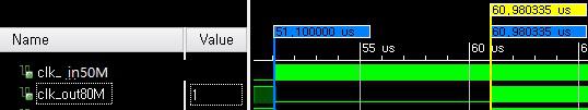
当你说时钟之间的“延迟”时,你不是指一个相位延迟,而是在输入时钟开始运行和输出时钟变得有效之间的延迟......(至少这是我从你的时间看到的
图)。
这是对MMCM的真实行为进行建模。
MMCM是一个基于PLL的时钟生成模块,需要时间来锁定输入时钟。
锁定所需的最长时间在数据表中指定 - 例如,对于Kintex-7,它位于DS189,表37,MMCM_Tlockmax中,指定为100us。
在您的模拟中,您只能看到10us;
仿真模型没有模拟完整的100us,因为这浪费了仿真时间......
但是高达100us是真实的,您需要在系统设计中考虑它。
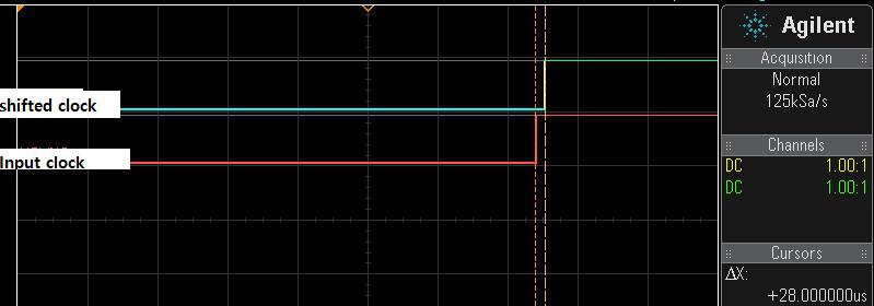
当锁定完成时,MMCM将发出LOCKED输出;
通常使用MMCM的!LOCKED输出作为MMCM输出时钟上运行的逻辑的复位生成机制的输入。
Avrum
在原帖中查看解决方案
以上来自于谷歌翻译
以下为原文
When you say "delay" between the clocks, you don't mean a phase delay, but a delay between the time the input clock starts running and the output clock becomes valid... (at least that is what I see from your timing diagram).
This is modelling the real behavior of the MMCM. The MMCM is a PLL based clock generation block that takes time to lock to the incoming clock. The maximum time required for the lock is specified in the datasheet - for example for a Kintex-7 it is in DS189, Table 37, MMCM_Tlockmax, which is specified as 100us. In your simulation you are seeing only 10us; the simulation model does not model the full 100us since that wastes simulation time...
But the up to 100us is real and you need to account for it in your system design. The MMCM will issue the LOCKED output when lock is achieved; it is customary to use the !LOCKED output of the MMCM as an input to the reset generation mechanism for the logic that is running on the of the MMCM output clocks.
Avrum
View solution in original post
当你说时钟之间的“延迟”时,你不是指一个相位延迟,而是在输入时钟开始运行和输出时钟变得有效之间的延迟......(至少这是我从你的时间看到的
图)。
这是对MMCM的真实行为进行建模。
MMCM是一个基于PLL的时钟生成模块,需要时间来锁定输入时钟。
锁定所需的最长时间在数据表中指定 - 例如,对于Kintex-7,它位于DS189,表37,MMCM_Tlockmax中,指定为100us。
在您的模拟中,您只能看到10us;
仿真模型没有模拟完整的100us,因为这浪费了仿真时间......
但是高达100us是真实的,您需要在系统设计中考虑它。
当锁定完成时,MMCM将发出LOCKED输出;
通常使用MMCM的!LOCKED输出作为MMCM输出时钟上运行的逻辑的复位生成机制的输入。
Avrum
在原帖中查看解决方案
以上来自于谷歌翻译
以下为原文
When you say "delay" between the clocks, you don't mean a phase delay, but a delay between the time the input clock starts running and the output clock becomes valid... (at least that is what I see from your timing diagram).
This is modelling the real behavior of the MMCM. The MMCM is a PLL based clock generation block that takes time to lock to the incoming clock. The maximum time required for the lock is specified in the datasheet - for example for a Kintex-7 it is in DS189, Table 37, MMCM_Tlockmax, which is specified as 100us. In your simulation you are seeing only 10us; the simulation model does not model the full 100us since that wastes simulation time...
But the up to 100us is real and you need to account for it in your system design. The MMCM will issue the LOCKED output when lock is achieved; it is customary to use the !LOCKED output of the MMCM as an input to the reset generation mechanism for the logic that is running on the of the MMCM output clocks.
Avrum
View solution in original post

 举报
举报